How to Install Auxiliary Lights on a Motorcycle: Mounts, Wiring, Switch
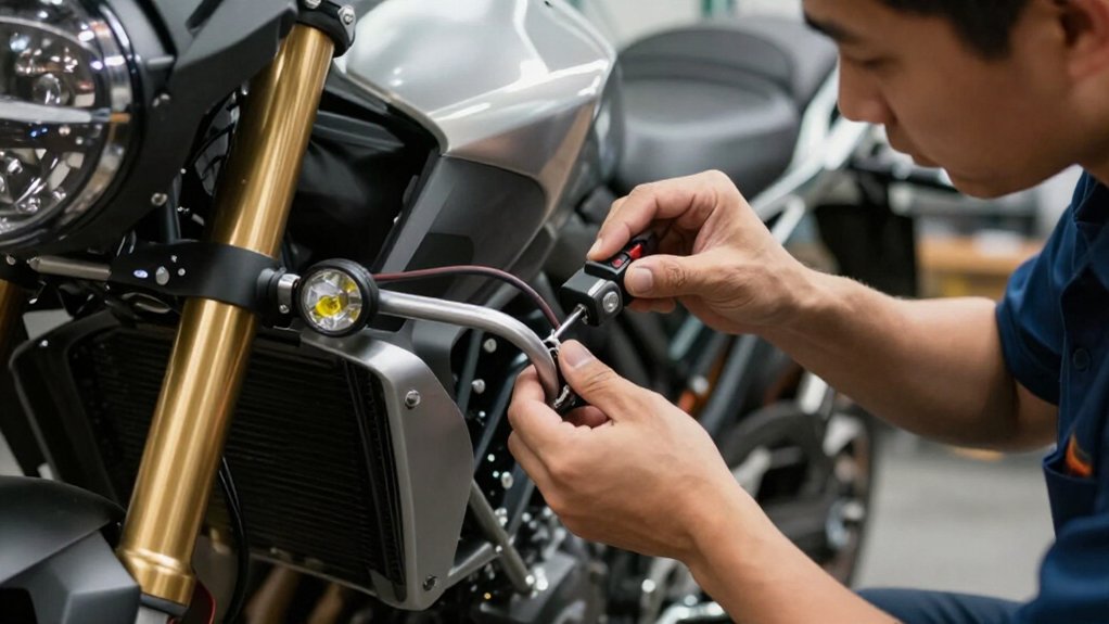
Mount auxiliary lights on rigid crash-bar, fork, or engine-guard brackets, then check full steering lock and suspension travel for clearance.
Before wiring, disconnect the battery’s negative terminal.
Use a fused 12-volt relay: battery positive feeds terminal 30, lights connect to 87, ground goes to 85, and a switched source plus handlebar switch triggers 86.
Route wires away from heat and moving parts.
Aim legally, test both lamps, and recheck bolts.
You’ll find more checks below.
Auxiliary Light Mounting Options
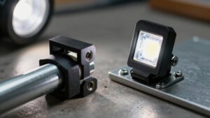
Choose rigid mounting points, such as crash bars, fork mounts, or engine-guard brackets, that won’t flex with suspension travel and shift the beam. Use adjustable brackets so you can aim each light after installation; make final beam adjustments at night, when you can see the pattern clearly. Before tightening hardware, loosely install the lights and check clearance around fairings, exhaust heat, and moving parts.
Turn the bars to full lock and cycle the suspension, confirming neither the beam nor wiring contacts anything or gets pinched. Position brackets where you can adjust them without removing bodywork, then mount the lights before routing the harness toward the battery. Keep cables clear of sharp edges and water spray, secure them against movement, and recheck fasteners after aiming.
Check Local Lighting Laws
Before wiring or using auxiliary lights on the road, check your local lighting laws. Requirements vary by location and motorcycle; verify rules before choosing a kit or aiming its lamps.
- Confirm permitted beam patterns, mounting height, aim, brightness, and required E-mark or DOT approval; compliant wiring won’t legalize an unapproved lens or bulb.
- Check whether you need an amber option, dedicated switch, or automatic cutoff or beam control to limit glare.
- Make sure you can follow use restrictions; some areas allow auxiliary lights only in fog, off-road, or at night, not continuously.
If rules aren’t clear, contact your DMV or police, or ask a licensed mechanic to check the bike and the kit’s markings. Record the applicable limits, then set and test the lights accordingly before riding.
Step 1: Disconnect the Battery First
To prevent a short, disconnect the battery’s negative (-) terminal before touching any wiring, then make sure the cable can’t spring back onto the post. Verify the cable stays clear while you route the auxiliary-light harness. With the battery connected, a slipped spade or ring terminal on a relay, switch lead, or ground can create a fault.
Don’t position or adjust these wires until the negative connection is secure and isolated. If your kit has an inline fuse, leave it out until you’ve finished routing the harness and crimping its connections. Once all wiring is complete, reconnect the negative terminal last. Then test the lights and switch before you tighten the mounts; this lets you confirm operation while you can still make adjustments. Keep the disconnected cable from contacting the post throughout installation.
Step 2: Gather Tools and Parts
Gather the lights, wiring, and mounting hardware before you start: fog LEDs provide a wide, short beam, while driving LEDs project a narrower beam farther ahead. Choose a wiring kit with a 12-volt automotive relay, typically rated 30 amps, a correctly rated inline fuse, and the matching switch harness. Keep the fuse within 6–12 inches of the battery’s positive terminal.
Set out crimpers, heat-shrink butt connectors and terminals, waterproof connectors, ring terminals, cable ties, electrical tape, and heat-shrink tubing. For mounting, gather brackets, bolts, washers, hand tools, and aim-adjustment hardware; you’ll align each beam before tightening the fasteners.
Identify a protected route that keeps wire leads clear of exhaust heat and moving parts. Replace damaged components before you reconnect the motorcycle battery.
Step 3: Route the Light Wiring
Plan the route before tightening any mounts, keeping wires clear of the exhaust, moving suspension parts, sharp edges, and chafe points. Trace the harness along the frame, checking each section for heat exposure, pinch risks, and abrasion. Route the main power lead from the inline fuse near the battery’s positive terminal back to the relay and light harness. Keep the fuse roughly 6–12 inches from the battery to protect the lead.
Run the relay’s trigger wire toward the recommended switched circuit, such as ignition or headlight power, so the lights operate only when the bike is on. Secure the harness with cable ties, snug but not crushing insulation. Leave small service loops where you’ll remove fairings or adjust light aim. Before reassembly, turn the handlebars fully and move the suspension through its range. Confirm wires stay clear, don’t bind, and won’t unplug.
Step 4: Connect Switch-Triggered Relay Circuit
With the harness routed and secured, disconnect the battery’s negative terminal before wiring the switch-triggered relay. Connect battery positive through an inline fuse to relay terminal 30; connect terminal 87 to the auxiliary lights’ positive leads. Ground terminal 85 to the battery negative or a clean, bare-metal frame point.
Feed terminal 86 from a switched 12-volt source, such as ignition or headlight power, and wire the handlebar switch in series with that trigger lead. Route the trigger wire away from hot surfaces and moving parts; secure it to prevent chafing or intermittent flicker. Reconnect the battery, then use a multimeter to confirm terminal 86 receives 12 volts when you press the switch. Verify continuity from terminal 30 to the lights when the relay clicks.
Step 5: Aim Lights Below Oncoming Drivers
Before riding at night, aim the auxiliary lights so their sharp upper cutoff sits below oncoming drivers’ sight lines. Park on a surface, 25 feet from a wall, with the bike upright and carrying your typical riding load. Mark headlight height, then set the auxiliary cutoff roughly 2–4 inches lower, about 1–2 degrees down.
Mount each lamp as low as practical without compromising the beam you need. At night, test the road edge and shoulder; adjust until light reaches them without washing across faces at typical oncoming headlight height. Choose the pattern: aim driving lights flatter and farther, while aiming fog lights wider and shorter.
Recheck with your load after suspension movement; braking or bumps can raise the beam and increase glare.
Step 6: Apply Dielectric Grease to Connectors
Clean and dry the connector contacts, then apply a thin layer of dielectric grease inside each connector housing, not directly to the mating metal surfaces.
For plug-and-splice or waterproof bullet connectors, coat both sides of the interface, especially if rain or washing may reach the wiring. After you crimp each joint, confirm its heat-shrink tubing fully seals the connection. Then slide the greased connector halves together to add another barrier against corrosion.
If your kit uses weatherproof relay or switch connectors, lightly coat their interfaces too; this helps limit oxidation and reduce the risk of intermittent connections.
Wipe away excess grease before joining the halves. Too much can keep a connector from seating, compromising contact and causing flickering. Keep grease out of the mating surfaces.
Confirm Both Lights Illuminate
Once the connectors are joined, turn the ignition on so the headlight trigger activates the relay, then press the handlebar switch and check that both auxiliary lights illuminate at the same time.
Keep the motorcycle upright and stable, with the transmission in neutral and the area clear. Stand to one side of the lamps; confirm each beam is genuinely on, not merely glowing dimly or reflecting from a loose mount. If only one works, inspect both lamp connectors for a fully seated plug and clean crimp/heat-shrink joints.
Verify the relay output feeds the left/right distribution harness and that its split hasn’t opened. Start the engine and repeat the test to reduce voltage-drop effects. If either lamp dims or flickers, check its ground/earth connection and confirm both grounds reach a solid chassis point.
Once both lamps illuminate consistently, adjust their aim separately using the aiming screws. Keep clear of traffic, moving parts, and exposed wiring throughout this check.
Diagnose a Blown Fuse
If your auxiliary lights stop working, check the inline fuse near the battery’s positive terminal; it protects the circuit closest to the +12V feed. With ignition or trigger switch on, test voltage on both fuse sides. If one side’s dead, trace upstream; if both sides are live but lights stay dark, inspect downstream. Replace it only with the harness/manual’s exact rating; never fit a larger fuse. Repeated failure usually means a ground short, pinched wire near fairing/frame edges, or faulty light/connector, not a weak battery.
| Check | Result | Next step |
|---|---|---|
| Side A | Dead | Upstream |
| Both sides | Live | Downstream |
| Fuse repeats | Short | Inspect |
| Rating | Match manual | Never upsize |
If it blows immediately again, stop. Check continuity and insulation at pinch points, light leads, and grounds. Work with care.
Recheck Mounting Bolt Torque
After a short test ride, recheck every auxiliary-light bracket bolt; vibration can settle the mount. Use the torque spec from your light kit or bracket manufacturer for the exact bolt size and thread, such as M6 or M8; don’t guess, because “tight” isn’t a torque value.
Before final torque, check that each bolt head and washer sit flat. Install threadlocker or locknuts only as specified, so the joint stays secure.
Aim each light where you want it, then torque the bolts; don’t torque a loosely positioned lamp and later alter its clamping force while adjusting aim.
After any initial night-time re-aiming, torque the fasteners again. Aim changes can shift loads through the bracket and mount. Use the specified value with a suitable torque wrench properly.
Conclusion
Before riding, aim your auxiliary lights without dazzling oncoming traffic, and check that local laws allow their use.
With the battery disconnected, secure the mounts, route wiring away from heat and moving parts, grease connectors, and install the specified fuse. Reconnect the battery and test both lights and the switch.
If a fuse blows, find the fault before replacing it. Recheck bolt torque after your first ride, then inspect the lights and wiring regularly.