What Size Wheel Ring Light Do You Need? 15.5 Vs 17 Inch Fit Chart
Choose a 15.5-inch ring if your rotor measures 14.8 inches or less and your rim/hub is at least 19 inches. Choose a 17-inch ring for rotors up to 16.5 inches and rims at least 21 inches.
These limits don’t guarantee fit: check caliper clearance, mounting depth, spoke openings, wheel offset, and inner-barrel taper.
Keep a gap so the ring won’t grind.
Before installing, verify kit voltage, control-box limits, fuse, and wiring capacity.
The checks below clarify fit.
15.5″ vs. 17″ Fit Chart
Which wheel ring light fits depends on your brake and rim measurements: choose a 15.5-inch ring if the rotor is no larger than 14.8 inches and the rim or hub area measures at least 19 inches; choose a 17-inch ring if the rotor is no larger than 16.5 inches and the rim or hub measures at least 21 inches.
Use the brake-assembly limits as a clearance check: the 15.5-inch ring accommodates assemblies up to 15 inches, while the 17-inch ring accommodates assemblies up to 16.5 inches. Match your measurements to the corresponding limits before ordering. Don’t pair an 18-inch wheel with a 17-inch light or choose another undersized combination; the ring may grind against the wheel and destroy the light. If either rotor or rim/hub requirement falls short, select a compatible size rather than assuming the larger ring will fit.
The chart’s minimum rim/hub clearance and maximum rotor size work together, so confirm both conditions for your setup. This distinction helps you avoid treating ring diameter alone as proof of fit, since brake clearance and rim or hub space each set a separate limit.
Measuring Wheel Diameter
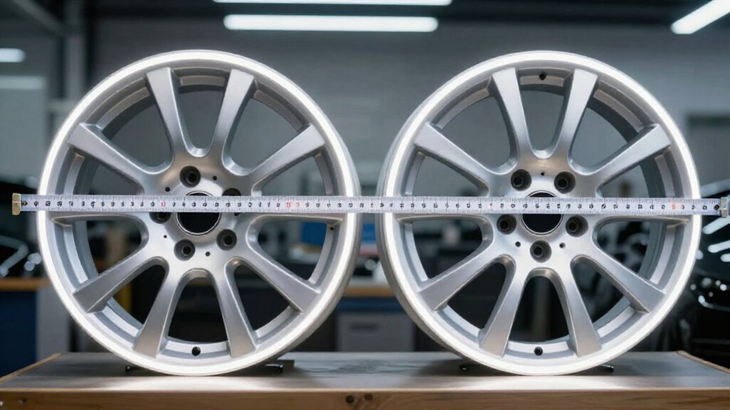
Measure wheel diameter by running a tape measure from one edge to the opposite edge through the center. This gives you rotor diameter for fit-chart checks; measure wheel width edge-to-edge and check spoke openings if your chart lists them. Compare rotor and rim hub measurements with the limits before choosing a light.
| Light | Max rotor | Min rim hub |
|---|---|---|
| 15.5-inch | ≤14.8 in | ≥19 in |
| 17-inch | ≤16.5 in | ≥21 in |
Use the chart’s thresholds: a 15.5-inch ring fits a rotor up to 14.8 inches, while a 17-inch ring fits up to 16.5 inches.
Also verify minimum rim hub diameter: at least 19 inches for the 15.5-inch model or 21 inches for the 17-inch model. Limits help you avoid grinding or damaging the wheel; don’t assume size proves compatibility.
Mounting Depth and Clearance
Even when a ring’s diameter matches your wheel, check the brake assembly’s mounting clearance before installation. Measure the widest points of both brake assemblies where the ring will sit; wheel diameter alone doesn’t establish fit. A 15.5-inch wheel light is intended for a rotor diameter of 14.8 inches maximum and a rim hub diameter of at least 19 inches.
A 17-inch light accommodates a rotor up to 16.5 inches and requires a rim hub diameter of at least 21 inches, so its mounting area needs more clearance. Mount the ring on the dust shield or hub assembly, and maintain a gap from the wheel to prevent grinding. Don’t force a smaller ring into place: inadequate clearance can grind the ring, damage wiring, and cause failure or shorting.
Voltage and Current Requirements
Check the manufacturer’s operating voltage and current draw per ring to confirm your power source supports either size; the 17-inch ring may draw more current because it has more LEDs. Keep the supplied fuse in-line and verify your wiring and connections can handle the rated load.
If you add brake or turn-signal functions, account for the powered control module and the added battery load.
Operating Voltage Range
Before connecting a wheel ring light, verify that your vehicle’s battery or 12V circuit falls within the kit’s specified operating voltage range; wiring it outside that range can damage the lights or control module. Check the label and installation manual for the permitted input range; don’t assume every kit accepts the same voltage just because it connects to a vehicle battery. Measure your supply under the conditions in which you’ll operate the lights, and confirm it stays within the listed limits before energizing the system.
If the kit includes a control box, verify its voltage requirement separately and match the vehicle circuit to that specification. Use the supplied fused power feed, such as a 10A fuse where specified, and install it as directed to interrupt power during a fault. Also confirm the power source and wiring can support the kit’s stated electrical load without excessive voltage drop. Don’t bypass protection or power the rings until these checks pass.
Current Draw Per Ring
For current draw per ring, use the exact kit’s control-module specifications rather than estimating from ring size alone. Match your ring size to the control-box model, then check its specified input voltage and maximum current rating.
LED count and wiring differ between kits, so those details determine actual draw.
For example, one MICTUNING 17-inch setup lists 612 5050 SMD LEDs and 1,780 lumens, compared with 564 LEDs and 1,645 lumens for its 15.5-inch version. The larger model typically uses more power, but brightness alone doesn’t establish current draw. LEDGlow kits include fused control wiring; a cited example uses a 10-amp fuse as the system’s practical circuit limit. Check the kit documentation, and keep power energized for brake or turn-signal functions, which affect operating draw.
Power Supply Compatibility
Although most wheel ring kits run on a vehicle’s 12V system, you must match the kit’s specified voltage and current requirements to its control box and harness.
The control electronics, including RGB modules, determine the required supply. Don’t assume rings of different sizes share the same electrical rating; check the product specifications for operating voltage and recommended current draw.
A supply that meets the voltage rating but can’t provide enough current may produce dim light or unstable modes. Confirm that your supply and the kit’s requirements align before connecting the harness. If you’ll use brake or turn functions, check whether the kit requires an energized feed and connect it to the constant-power or signal circuit. Verify compatibility before installation to support operation and prevent overheating.
Fuse And Wiring Capacity
Check the kit’s inline fuse and wiring rating before installation; many systems use a 10A fuse, which protects the control box and harness from excess current. Match voltage and current requirements to your control system and harness; each supports a specific amperage load, such as a 10A-rated setup. Use the supplied power cord and fuse; don’t bypass either, because your brake, turn-signal, and light functions rely on the supply.
Confirm your circuit’s wire gauge and fuse type against the kit’s specifications. If you’re using an app- or Bluetooth-controlled version, verify that its power supply delivers the required current without tripping the fuse’s overcurrent protection. If the fuse opens, switch off power and replace it with the specified rating; don’t install a higher-rated fuse or bypass protection.
Battery Load Impact
Beyond fuse and wiring capacity, consider how each ring size loads your vehicle’s battery. Your control box typically draws power through a fused input; some kits use a 10A fuse to limit current through battery wiring. Actual draw depends largely on LED count. A 17-inch kit may contain 612 5050 SMD LEDs, compared with about 564 in a 15.5-inch kit, so it can demand slightly more power at full brightness. That difference may also appear in rated output: roughly 1,780 lumens versus 1,645.
Keep your battery and wiring near a steady 12V under load for reliable colors, chase patterns, scans, and sound-react modes. Verify fuse rating and wire gauge for expected current; otherwise, lights may brown out, flicker, or trigger protective shutdown during operation.
Verify Brake Caliper Clearance
Measure the brake assembly at its widest point to confirm the ring clears the caliper and rotor. Check the LEDGlow fit chart before choosing a size. Its 15.5-inch rings accommodate rotors up to 14.8 inches and require a rim or hub diameter of at least 19 inches. Its 17-inch rings accommodate rotors up to 16.5 inches and require a rim or hub diameter of at least 21 inches.
Measure your actual setup rather than relying on a model name or assumption, then compare both measurements with the limits for the closest size. A ring that’s too small can contact the brake assembly; rotation may grind the light and potentially rip its wires. Don’t install a ring unless you can verify adequate clearance throughout the assembly. Recheck dimensions if components have changed. Recheck after brake or rotor modifications to confirm clearance again.
Account for Split-Spoke Designs
Split-spoke designs can narrow or shift the opening where a wheel light sits, so wheel diameter alone won’t confirm fit. Measure the distance between your spokes and check that the ring clears every cutout and sits evenly.
Use the fit chart to select a mounting diameter: a 15.5-inch light targets a rotor diameter of 14.8 inches or less and a rim hub diameter of at least 19 inches. A 17-inch light targets a rotor diameter of 16.5 inches or less and a rim hub diameter of at least 21 inches. These limits don’t guarantee clearance if spoke protrusions sit close to the brake assembly.
Test-fit the ring against the widest parts of both brake assemblies, then confirm a small gap remains between the wheel and light throughout rotation. Proper installation helps prevent rubbing, grinding, and ring damage.
Aftermarket Wheel Offset Changes
Aftermarket wheel offset can change ring-light clearance even when you keep the same 15.5- or 17-inch size. Offset changes how your wheel and tire sit inboard or outboard, shrinking or increasing clearance between the brake assembly, dust shield, and ring light.
If your offset moves the wheel closer to the shield or rotor, a 17-inch ring may become too tight. Check limits: rotor diameter ≤16.5 inches and rim-hub diameter ≥21 inches.
An outward offset usually makes fit easier, but brake width and mounting at the shield or hub can shift contact points. After any offset or spacer change, recheck the widest part of both brake assemblies; fit depends on clearance, not vehicle model. Leave a small wheel-to-light gap so suspension movement won’t cause rubbing.
Prevent Wiring Chafe
To prevent wiring chafe, route the harness along the bracket and hardware path, leaving a small slack loop so wheel movement won’t pull it tight. Use supplied clip-on brackets and pre-drilled holes to secure the wire near the dust shield and hub. Keep it clear of the tire sidewall and moving suspension parts.
- Place connector points and any junction cable, including a four-port unit, where they can’t rub the ring, spokes, or shield edges.
- Follow manufacturer guidance for brake/turn power so you won’t repeatedly reroute an energized cord.
- Turn the wheel fully left and right; verify the harness can’t contact the ring or rotor, where abrasion can expose conductors and cause shorts.
Recheck clips after installation, and replace damaged insulation before powering the lights.
Measure Inner Barrel Taper
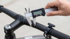
Measure the inner barrel taper with a caliper or tape by recording the inside diameter at the outer lip and again farther in, where the barrel narrows. Note how quickly it narrows, and mark the tightest point; the outer lip alone won’t confirm clearance. Compare the taper trend with your ring’s required clearance so it won’t sit inside the narrowing section.
- Record the widest inside diameter at the outer edge and the narrower diameter farther in.
- Check if taper reduces back-side clearance, pushing the ring toward the brake assembly and increasing contact risk.
- Compare readings with fit limits: 15.5-inch lights need Rotor Dia. ≤ 14.8 and Rim Hub Dia. ≥ 19; 17-inch lights need Rotor Dia. ≤ 16.5 and Rim Hub Dia. ≥ 21.
Check clearance throughout.
Conclusion
Choose a 15.5-inch or 17-inch wheel ring light only after you measure the wheel’s diameter and available mounting depth. Check caliper clearance, inner-barrel taper, and split-spoke access; don’t assume the face opening tells the whole story. Confirm your wheel offset and the light’s voltage and current requirements, then route wiring away from moving or hot parts to prevent chafe.
If measurements fall near a limit, verify fit with the manufacturer before you buy or install.