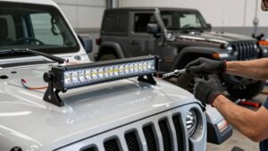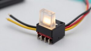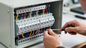
How to Wire Off-Road Lights With a Relay and Switch (Wiring Diagram)
Disconnect the battery negative cable.
Fit a fused relay near the battery.
Connect battery positive through an appropriate fuse to terminal 30, then terminal 87 to the light bar’s positive lead. Ground the light bar’s negative lead.
Connect terminal 86 to ground, and route a switched 12-volt trigger through the dash switch to terminal 85. The switch controls only the coil, not lamp current.
Seal connections; reconnect power and test.
More checks ensure dependable operation.
Relay-And-Switch Wiring Diagram
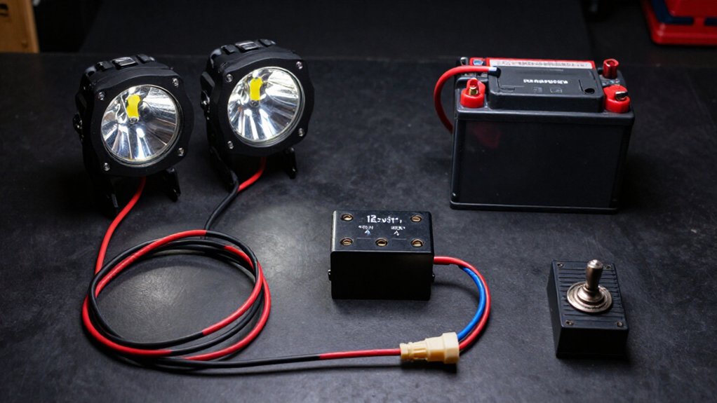
Wire the relay so it carries the light bar’s high current while the dash switch controls only the relay coil. Connect battery positive to terminal 30, then run terminal 87 to the light bar’s positive lead. Keep this output path rated for the bar’s draw.
Connect a switched trigger to terminal 85, with the dash switch in series so switching off leaves terminals 30 and 87 open. Ground terminal 86 to complete the coil circuit. Connect the light bar’s negative lead to chassis ground; don’t send its operating current through the dash switch.
If you’re using a headlight trigger, tap headlight positive into the trigger feed and headlight negative to trigger ground. The relay then energizes only when that headlight circuit is active.
Gather Tools and Wiring Diagram
Before connecting the relay, gather a relay harness, an in-line or dash switch, a fuse and wire sized for the light’s current, and crimping tools. Use terminal markings to map switched power through 30→87, while 85/86 carries the low-current trigger so your switch doesn’t carry the lamp load.
- Mark battery + to relay power input and identify a reliable ground point.
- Trace the light bar’s positive lead to 87, and its negative lead to ground return.
- Match fuse and wire gauge to current: small pods may draw about 1.4A, while large bars can approach 40A.
Lay out the harness in diagram order, then use a continuity check to confirm the switch opens and closes the trigger line before applying power; inspect crimped joints and insulation.
Step 1: Disconnect Negative Battery Cable
To prevent an accidental short, disconnect the battery’s negative cable before handling the relay power terminals.
Loosen the clamp on the negative (−) post, then lift the cable clear and secure it so it can’t spring back into contact. Before proceeding, verify power is off: check that battery-powered accessory lights and dash indicators behave normally.
Don’t begin relay-terminal wiring until the cable stays isolated from the post.
With the negative cable secured away, connect relay terminals 30/87 to the light-bar circuit and terminals 85/86 to the trigger circuit. Keep your hands and tools clear of exposed conductors while you work.
Reconnect the negative cable only after you’ve routed all wiring, secured all crimp or screw connections, and covered exposed conductors with heat-shrink tubing or tape.
Step 2: Mount the Relay Near Battery
Mount the relay within a few inches to about a foot of the battery in a solid, dry spot to keep the high-current wiring from terminal 30 to 87 short and limit voltage drop. Secure it with the supplied bracket and screws or a firm tie-down so vibration can’t loosen the mount. Keep the relay clear of exhaust heat and likely splash, and position it where you can inspect it without disturbing other wiring.
Route the terminal 30-to-87 output conductors together, away from sharp edges and hot engine parts. Protect them with loom, and fit grommets wherever they pass through a firewall or bulkhead. Install an appropriately sized inline fuse in the battery-positive feed to terminal 30 before it reaches the relay itself.
Step 3: Connect Switch Trigger Lead
With the battery disconnected, locate relay terminals 85 and 86, then route the vehicle’s trigger wire, such as a high-beam or backup-light tap, through the dash switch so the switch output feeds terminal 85; connect terminal 86 to ground as the relay labeling specifies.
If your harness uses a vehicle trigger lead, identify its source and cut it after confirming the circuit. Route the source side to the switch input; connect its output to 85. The switch must interrupt the trigger lead, not the main lamp-power path.
With the switch OFF, the coil stays open and contacts 30 and 87 remain open. Turn it ON and listen for a relay click. Insulate unused terminals separately; secure wiring from heat and moving parts. Test both switch positions.
Step 4: Feed Lights From Relay
Once the switch controls the relay coil, wire the high-current feed: connect terminal 30 to battery positive through a fuse sized for the load, and terminal 87 to the light bar’s positive input.
Run the light bar’s negative lead to a chassis ground or battery negative; don’t route it through the relay. Terminals 85 and 86 operate the coil, while contacts 30 and 87 carry the lights’ full current when energized.
Choose a relay, fuse, and wire gauge rated for the load: a 1.4-amp pod needs less capacity than a 40-amp bar. Keep the fused supply close to the battery, protect wiring from abrasion and heat, and use weather-resistant connections. Put the dash switch in series with the coil trigger, not the high-current lamp feed.
Step 5: Test Switch Operation
To test switch operation, turn the dash switch ON and listen for the relay to click, which confirms the control circuit is energizing the 85/86 coil. With the harness installed, keep 30 and 87 connected to the light bar and confirm a solid ground. Switch ON: the lights should illuminate only while the dash switch is ON.
Verify battery voltage at the 30-to-87 output when the relay closes; it should disappear when you switch OFF. If the relay clicks but the lights stay dark, check the load connections and ground. If it doesn’t click, ensure the switch provides terminal 85, not 30/87, so the contacts stay open until the coil energizes. Finally, turn the vehicle OFF and disable the relay; confirm no power back-feeds and drains the battery with the vehicle parked safely.
Step 6: Heat-Shrink Exposed Connections
After confirming the relay and switch operate correctly, seal each crimped connection with heat-shrink tubing to protect it from moisture and corrosion. Slide tubing over each joint after crimping, choosing a diameter that fits tightly over the insulation before heating. Use a heat gun, not a torch, and keep it moving to prevent overheating relay pins or melting nearby plastic connectors.
Ensure the tubing extends past both sides of the crimp or terminal barrel, enclosing all exposed metal. If your harness instructions call for insulating disable terminals, cover each exposed terminal with heat-shrink, not tape alone, so metal tips can’t contact adjacent terminals. Let the tubing cool, then tug-test each connection and inspect both ends. No copper should remain visible before routing the harness.
Measure Voltage at Lights
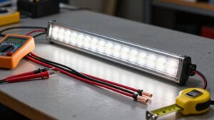
With the engine running, set your multimeter to DC volts and measure directly across the light bar’s power wires at the lamp connector, with the light switched on. Expect about 13.5–14.7 volts under load. A lower reading, especially a drop exceeding 0.5–1.0 volt, suggests excessive resistance, a poor crimp, or a faulty connector.
Keep probes clear of moving parts and prevent them from bridging terminals. To locate positive-side loss, compare battery positive to pin 30, then pin 87 to the lamp’s positive lead. A sharp sag when switched on points to the feed, fuse, relay contacts, connections, or trigger circuit.
Turn the circuit off before altering wiring; retest afterward. Measure with the connector connected so the circuit remains loaded, and avoid touching exposed conductors.
Relay Ground Connection Checks
Check the relay coil ground/return, typically terminal 86, first; a weak connection can stop the 30–87 contacts from engaging. With power isolated, trace pin 86 to battery negative or clean chassis metal. Measure continuity; expect close to zero ohms. Ensure the trigger circuit ground and coil ground share a common reference; ungrounded references can prevent current through 85/86 from energizing the coil.
| Check | Test |
|---|---|
| Ground path | Confirm close to zero continuity |
| Shared reference | Match trigger and coil grounds |
| Output check | Verify voltage at terminal 87 |
| Light negative | Ground separately as specified |
After wiring, switch on the trigger. Listen or feel for a relay click, then confirm voltage at terminal 87. Ground the light bar’s negative harness lead to battery or chassis as specified; that return is separate from the relay coil ground. Avoid short-circuiting the terminals.
Inspect Wiring for Corrosion
Before applying power, inspect relay-to-light and battery-to-relay terminals, especially terminals 30 and 87, for white or green residue, pitting, or dark oxidation. Check crimp joints, wire ends, and ground connections at relay terminal 86 and the light-bar negative for loose crimps or exposed copper; moisture there can accelerate corrosion and voltage drop.
Confirm the harness uses sealed, insulated connectors or heat-shrink over crimps, and replace any section with cracked insulation. Inspect beneath split loom and tape for rust trails, dampness, or sticky residue; trapped water near relay and fuse holders invites corrosion.
With the light bar running, perform a multimeter voltage-drop test across the power and ground path. A noticeably high drop points to resistance; clean or replace the affected connection before continued use.
Conclusion
Before you power your off-road lights, verify the wiring diagram, fuse rating, and every connection. Disconnect the negative battery cable before servicing the circuit, and mount the relay close to the battery. Confirm the switch trigger and ground paths, then heat-shrink exposed joints.
After reconnecting power, measure voltage at each light and inspect wiring for corrosion or damage. Don’t operate the lights until voltage and relay grounds check out safely and consistently under load conditions.