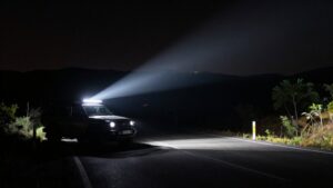
How to Wire an LED Light Bar to Your High Beams (Trigger Wire Method)
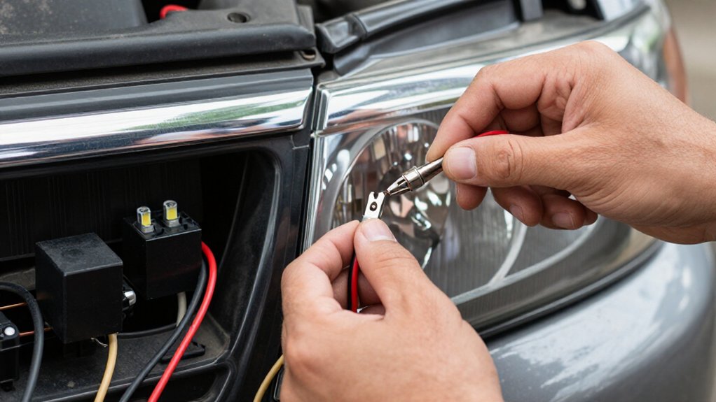
To wire an LED light bar to high beams, use the beam circuit only as a relay trigger; power the bar through a fused battery lead.
With the truck off, disconnect the negative battery cable.
Use a multimeter to identify a trigger that changes state with high beams, confirming whether it switches positive or ground.
Connect the relay coil, ground the bar, and route wiring in loom.
Test low-beam dropout.
Then find more setup and troubleshooting details below.
Identify High-Beam Trigger
Before wiring the light bar, use a multimeter to probe the headlight harness or fuse box and find a signal that switches with the high beams. Set the meter to measure DC voltage, then connect its reference lead to ground. With the high beams off, probe wires at the harness or fuse box; avoid piercing insulation where possible, and keep the probe clear of moving or hot parts.
Turn the high beams on and watch for a change from 0 volts to battery voltage. Turn them off and confirm the reading returns to 0 volts. This change identifies a positive trigger. Some vehicles switch the lamp on the ground side instead, so check for a negative trigger: the circuit changes to ground when high beams activate. Record wire and switching behavior. Use that high-beam wire only as the relay coil’s trigger reference, not as the light bar’s power feed.
Gather Wiring Tools and Materials
Gather a light bar rated for your truck and a wiring harness with a relay and fuse sized for the bar’s current draw and wire gauge. Before installation, check the manufacturer’s instructions and confirm the harness supports truck mounting and the selected bar.
- Keep wire, ring terminals, and ground hardware on hand for a secure connection to a clean chassis point.
- Set out a screwdriver, wire cutters, wire strippers, and a multimeter for careful connection and circuit checks.
- Verify the specified fuse rating, then identify the power source and high-beam trigger wire before routing.
Use the meter and vehicle wiring information to confirm the trigger wire; don’t rely on color alone, since wire colors and circuits can vary by model and trim level too.
Step 1: Disconnect Battery Negative
Turn the truck off and disconnect the battery’s negative (–) terminal to reduce the risk of short circuits while wiring the relay and high-beam trigger.
Use a wrench to loosen the negative terminal clamp, then lift the cable clear of the battery post. Route it away from the battery and secure it so it can’t spring back and make contact.
Keep the ignition key out of the on position while you work; this prevents accidental energizing of the headlight circuit you’ll later use as the trigger reference. Before proceeding, verify with a multimeter that the battery’s disconnected negative post has no continuity to chassis ground.
Reconnect the negative terminal only after you’ve fully installed and secured every relay, fuse, and light bar harness connection in place.
Step 2: Choose Light Bar Mounting Position
With the battery still disconnected, choose a secure, vibration-resistant mounting position that won’t obstruct your view, restrict airflow, or interfere with moving parts. Consider roof mounting when you need maximum road reach. A bumper or grille location may be easier to access and better protected, depending on your truck’s clearance and brush guards.
Before drilling, verify adequate space behind the bar for its harness and connector, plus room for brackets and fuse/relay placement. Check the bar won’t contact headlights or trim as the suspension moves, and confirm the harness can follow a clean route without pinching.
Aim the beam forward, then set its height within local legal limits to reduce glare for oncoming drivers. Keep the assembly clear of panels and service access points.
Step 3: Connect Relay Coil Trigger
Once the light bar is mounted, identify the high-beam trigger wire with a multimeter at the headlight harness or fuse box, and confirm it reads 12 volts only when the high beams are on. Before connecting, consult the harness diagram and identify the relay-coil terminals. Attach one coil lead to the verified trigger wire with an automotive-rated connector.
Connect the other to the ignition-controlled or accessory source specified for your harness and relay. If the relay uses separate ground control, secure that lead to bare chassis metal. Insulate connections and route wires away from heat and moving parts. Restore power, switch on the high beams, and verify the relay clicks and the bar illuminates.
If it doesn’t, switch off and check the coil connections.
Step 4: Connect Fused Battery Power
Run a dedicated positive wire from the battery through an inline fuse sized to the light bar’s specified current draw, placing the fuse as close to the battery terminal as practical. Check the bar’s label or instructions for its amp rating, then select a matching fuse. Choose automotive wire sized for amperage and run length; 14–10 AWG may suit your installation safely.
Connect the fused lead to the harness’s power input, often the relay’s output, and observe polarity. Route the wire through a grommet wherever it crosses metal, protect it with loom, and secure it along the frame away from heat and moving parts. Verify battery voltage at the fused lead with a multimeter before testing it.
Step 5: Aim the Beam Pattern
Aim the bar on level ground so its lens faces forward, clears the roof line, and sits level from side to side. Follow the manufacturer’s specified mounting height; this helps keep the beam’s hot spot on the roadway rather than in oncoming drivers’ eyes.
For a wall check, park your truck 25 ft (about 7.6 m) from a flat wall on level pavement. Mark the aiming height and compare the beam center with that line. Loosen the brackets and adjust in small increments, typically 1–2°, until the brightest area sits slightly below the headlight beam centerline on the wall.
Tighten the mounting hardware, then check the pattern again; tightening can shift aim. Recheck after suspension changes or when cargo alters the truck’s stance.
Step 6: Seal Wire Entry Points
After confirming the light bar’s aim, seal every harness entry point through the vehicle with electrical-grade silicone or a rubber grommet to keep water out. Before closing each opening, apply dielectric grease to exposed roof or bumper connectors to limit corrosion from moisture and road spray. Cover any splice at an entry point with adhesive-lined heat-shrink tubing; heat it evenly until the liner seals around the insulation.
Install the grommet or apply silicone per product directions, maintaining a continuous seal without blocking factory vents or drains. Keep the harness clear of moving parts and sharp edges. Secure wires with clamps 6–12 inches from each opening to prevent chafing and strain on the seal. Allow silicone to cure, inspect the entry for gaps before driving.
Verify Low-Beam Relay Dropout
With the vehicle safely parked, switch from high beams to low beams and confirm the light bar turns off immediately.
Use a multimeter or test light at the relay coil trigger wire: voltage should be present on high and disappear on low, allowing relay dropout.
If the bar stays on briefly or partially, check for a retained high-beam signal, misidentified headlight wire, or poor relay or connector contact. Confirm negative/negative trigger wiring: selecting low beams must remove the trigger; wrong polarity can prevent dropout.
Repeat high-to-low-to-high cycles; verify consistent shutoff on low before finalizing installation. Probe carefully, use the meter’s appropriate range, and avoid adjacent terminals. Don’t let the test lead bridge contacts. Recheck connections before securing wiring and restoring normal operation. Keep the vehicle parked throughout testing.
Diagnose Relay Chatter
Relay chatter usually points to an unstable or weak trigger signal, poor connections, or a wiring mismatch. With high beams on, use a multimeter to confirm the trigger wire switches 12V, or provides the specified ground reference, under load. Verify the relay coil voltage, polarity, and contact pinout against your harness diagram.
Measure coil voltage while the high beams are on; a drop indicates trigger-path resistance. Check relay and light-bar grounds and crimps; loose connections can cause voltage drop and rapid clicking.
| Symptom | Check | Action |
|---|---|---|
| Chatter under load | Trigger voltage | Repair signal path |
| Chatter with load off | Power or ground | Isolate circuit |
If chatter persists, fit the correct inline fuse and inspect wiring for shorts or intermittent contact. Disconnect the light-bar load to isolate a power or ground fault. Switch off power before changing connections. Retest afterward.
Inspect Relay Socket Corrosion
If relay chatter persists despite a stable trigger signal, inspect the relay socket for corrosion that can interrupt current even when the relay clicks.
Before you work, switch off the light bar and disconnect the battery’s negative terminal. Pull the relay straight out, then inspect its pins and socket contacts for green or white deposits, rust, or heat discoloration. Check that each socket terminal grips firmly; pitting or looseness can compromise conductivity despite an audible click.
Clean corrosion with contact cleaner and a non-metallic abrasive, then dry thoroughly before reinstalling. Verify low resistance, typically near 0–5 Ω where appropriate, between the socket terminal and connected wiring, ground, or power path. Apply a thin dielectric-grease coat to limit moisture and deter future corrosion from recurring.
Conclusion
Before you finish, verify the trigger wire switches the relay only with high beams on and drops out when you select low beams. Check every crimp, fuse, ground, and sealed entry point, then test the bar stationary.
If the relay chatters or the socket shows corrosion, don’t drive until you correct the fault. Reconnect the battery negative last, and aim the bar without dazzling other road users. Follow the wiring diagram.