How to Choose a Switch Panel for Off-Road Lights: Gangs, Amps, Controls
Choose a panel with one gang for each independently controlled lighting zone, plus a spare or two for future upgrades.
Add each lamp’s wattage and divide by system voltage to estimate circuit amps.
Size fuses and wiring for each load, and verify the main feed handles all zones running together.
Use switches to trigger relays, not carry high lamp current.
Pick sealed, glove-friendly controls you can reach, then check mounting, service parts, and battery compatibility.
Use the details to finalize your setup.
Gang Count and Amp Draw
When choosing a switch panel, match its gang count to the number of independent light circuits you want to control, such as a light bar, bumper pods, or rock lights, and keep one or two switches spare for future additions. Estimate your current draw for each circuit by adding each lamp’s watts and dividing by system voltage; account for startup surge, especially with LEDs.
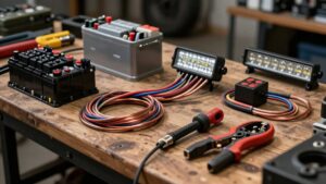
Use separate fused relay circuits for high-draw gangs, so panel switches operate relay triggers rather than carrying lamp current. Confirm the panel’s total and per-switch ratings exceed relay-trigger current; size fuses and wiring for each circuit’s load. Keep lamp draw comfortably below its fuse rating, choosing an appropriate fuse, often 10–30 A, and wire gauge matched to circuit amps for safe, reliable protection.
Glove-Friendly Control Access
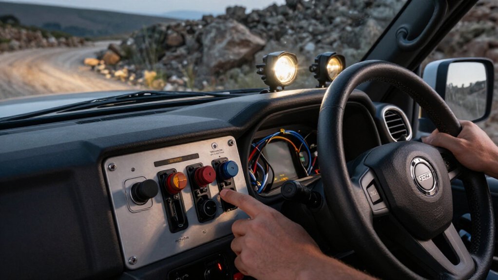
Within easy reach of the driver’s seat, a switch panel lets you control lights without taking your hands off the controls for long. Choose a gang panel mounted on the driver-side lower dash or center console, where you can reach it comfortably while maintaining vehicle control. Use backlit rocker switches with clearly labeled legends or high-contrast labels; dark markings can disappear when you’re wearing insulated or off-road gloves at night.
Select actuators that don’t demand fingertip precision. A positive click and consistent travel help you confirm each circuit change by feel, reducing fumbling and distraction. Group lighting by zone, so you need fewer switches and can identify the intended circuit quickly, even with muddy gloves. Check labels and switch positions before driving.
Weatherproofing and Vibration Resistance
After confirming the panel is easy to operate with gloves, check that it can withstand water, grit, and trail shock. Choose a fully enclosed panel rated IP67 or better with sealed rockers and a gasketed face to keep mud and wash water out.
Inspect corrosion-resistant fasteners, nickel-plated terminals, and sealed connectors; salt, condensation, and grit can cause intermittent faults. For trail vibration, choose a rigid steel or aluminum base, reinforced standoffs, and vibration-rated mounting. Add strain relief at harness entries, then secure loom every 6–8 inches. Confirm operating temperature range and switch cycle rating before installation.
| Check | Look for | Why it matters |
|---|---|---|
| Seals | IP67+ rockers | Block water and grit |
| Hardware | Plated terminals | Resist corrosion |
| Mount | Rigid base | Limit shock damage |
| Harness | Strain relief | Reduce wire fatigue |
Wired vs. Wireless Controls
Wired controls give you direct, dependable switching without Bluetooth pairing, while wireless controllers can group light zones into presets. Compare their response, range, and troubleshooting needs.
Use relays and fuses to switch high-current loads with either setup. Choose wired for immediate hands-on control or wireless if you can manage battery and pairing requirements.
Wired Control Reliability
When dependable lighting control matters, a wired gang switch panel is typically more reliable than a wireless controller because each switch activates a relay-protected circuit without relying on radio reception or controller batteries. For high-current lights drawing 30–60 amps per circuit, route load current through the fused battery feed; the panel switch should energize only the relay coil.
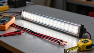
Before final assembly, test each channel with a multimeter for continuity and voltage, then verify that each relay operates. If a fault develops, isolate it to a switch output, relay, or fuse, and check wiring continuity rather than troubleshooting an intermittent control link. This direct, testable path makes wired control a practical choice when consistent illumination matters.
Wireless Setup Options
For most off-road lights, a wired panel offers simple, interference-resistant control by triggering a relay for each circuit.
A wireless key fob or controller sends commands to a receiver that switches relays or outputs for light zones. It can reduce wiring, but you must manage batteries and choose receiver placement. Match the panel’s or receiver’s control voltage and trigger type to your relay and fuse arrangement; a low-voltage logic signal isn’t interchangeable with a relay-trigger output. Keep the lighting power path fused.
For either control method, give each load its own fused relay output, including an LED bar, ditch or bucket pods, and rock lights. Label wireless zones: front, rock lights, or underglow, and run power from the battery through a fuse block to each light group.
Response Time And Range
A wired panel triggers its relay with virtually no perceptible delay, while a wireless controller can add tens to hundreds of milliseconds depending on signal strength. Its switch sends a signal through the harness directly to the relay coil. Wireless range varies: line of sight generally gives the strongest link, while an enclosed cabin, roll cage, or heavy RF noise can reduce a quoted “up to” distance sharply.
If you mount controls deep in the dash or behind metal, those barriers can weaken radio or Bluetooth reception; a wired signal doesn’t depend on a radio link across the vehicle. Wired panels show status with an LED. Wireless app or dashboard feedback may lag when the connection drops or becomes intermittent. Verify activation before moving.
Choosing The Right Control
Choose wired controls for maximum reliability and simple operation: a gang switch panel sends a low-current trigger to relays, keeping high current out of the dash switches.
Choose wireless controls such as Bluetooth when you need app-based or multi-zone operation. They add pairing and control management, and they still need fused power and relays to handle LED bar or pod current safely.
Plan each lighting circuit with its own switch and fuse; combining high-draw zones can overload wiring or complicate fault diagnosis.
For a roof bar, spot or fog pods, and rock lights, wired switching gives immediate, clear control of each zone without depending on signal range or device connectivity. Wired controls tend to withstand off-road vibration and weather consistently.
Use wireless for show-style or noncritical zones when convenience outweighs connectivity limits. Either way, verify relay ratings, fuse sizing, and wire gauge before installation.
Lighting Setup Priorities
Group your lights by zone, count the circuits you need, and add one or two spare switch positions for future upgrades. Size the panel for the maximum combined current draw, with each high-draw circuit on its own correctly rated fuse and relay.
Choose backlit latching switches and a mounting location you can reach safely while driving.
Circuit Count
Before selecting a switch panel, list every planned light zone—such as a front light bar, bumper pods, rock lights, or underglow—then add one or two spare switches for future upgrades.
Treat each independently controlled light zone as a circuit unless you routinely run zones together. Group those lights on one switch to keep operation simple; retain separate control where beam direction or use differs.
Select a panel with enough positions for your priority zones today, plus room for next season’s additions such as ditch lights or another whip style. Give each high-draw zone its own fused output, so a fault or accessory demand won’t overload or restrict another circuit; follow the panel maker’s wiring and fuse specifications, and secure all connections.
Total Current Draw
Once you’ve listed your light zones, add up each light’s amperage—amps = watts ÷ volts—to estimate total draw.
Prioritize high-draw loads first: LED bars and pods usually dominate current compared with small indicators. Add their amperage ratings to determine the combined load for zones you run together, such as a front bar and bumper pods.
Choose a panel whose outputs and wire capacity can handle that load.
Size each circuit’s fuse to protect its wiring; select a rating slightly above steady draw when the equipment maker permits, so operation won’t cause nuisance trips.
Confirm the main feed supports your worst-case combined current, not one circuit. If you’re likely to add lights, reserve one or two unused circuits and verify feed capacity remains adequate.
Control Preferences
After confirming the panel can handle your combined current, match its switch count to your planned lighting zones, such as a front LED bar, bumper pods, and rock lights, with one or two spare positions. Choose latching rockers for steady lights and momentary controls for strobe triggers. Assign each circuit a fused output and relay; high-draw bars and pods typically need dedicated relays rather than direct switch loads.
Keep routine trail lights on fixed, intuitive controls and reserve optional channels for color changes or multi-zone effects. Backlighting and clear labels help you identify functions at night; glove-friendly controls reduce accidental activation. Test every function before driving and verify labels match loads; don’t rely on color alone to distinguish switches when operating in darkness.
Mounting Location
Mount the panel within arm’s reach so you can operate it without taking your eyes off the trail.
Choose a position that stays visible to your hand but doesn’t block your view or interfere with switches. Keep it above areas where boots can strike it or water can soak it. In a truck or Jeep, the lower driver-side dash or center console provides access and a route for wiring. In a UTV, attach it to a dash bar or cage bracket with hardware; vibration can loosen switches and connectors.
Secure the panel before connecting the harness.
Protect wiring immediately as it leaves the panel. Fit grommets at openings, cover the harness with loom, and route it away from heat and moving parts. This reduces abrasion, shorts, and failures that disable lights.
Vehicle-Specific Mounting Requirements
Choose a mounting spot you can reach easily from the driver’s seat, such as the lower dash, center console, or UTV dash bar, without blocking your view or interfering with factory controls. Then match the panel’s form factor to your vehicle’s available space, and confirm you can reach its outputs and connectors for service. Mount it on a rigid bracket secured to structural points; trail vibration can loosen unsupported hardware. Choose a sealed, waterproof and dustproof panel, and keep it clear of direct spray and heat from exhaust or manifolds.
Plan routes for each light zone around cab or bed layouts. Use protected loom and grommets, avoid moving parts and pinch points, and leave wiring slack for trimming, re-looming, or added circuits when needed.
Replacement Parts Availability
Even a reliable switch panel can fail, so check that its manufacturer stocks individual switches, backlit labels, protective covers, and compatible relays and fuse holders. Choose a model with documented service parts so you can replace a failed switch instead. Confirm it uses standard replaceable modules, not a sealed one-piece unit, and matching components remain available years later.
Verify replacement relays, fuse holders, and circuit-breaker blocks match the harness and pinout. If you expand circuits, choose a panel with a pre-wired, labeled harness; confirm you can buy replacement harnesses or plug/socket connectors separately. Before purchase, check OEM-style part numbers and warranty coverage for wear items such as switches and indicator LEDs. Compatible spares reduce downtime and help you restore lighting safely without panel replacement.
Poorly Sealed Circuit Breakers
Beyond sourcing replaceable parts, check how well the circuit breakers resist water, dust, and vibration.
Water or grit entering an unsealed body can corrode contacts, causing intermittent trips or failure when your lights draw peak current.
Choose a breaker rated for wet, dust-prone, high-vibration conditions; repeated splashing, mud, and pressure washing can degrade insulation and trigger nuisance faults.
- Look for a fully enclosed, gasketed housing resistant to vibration.
- Match its amperage to your wire gauge and circuit’s expected current.
- Mount it clear of standing water; inspect tight terminals and ring connections.
An undersized breaker or loose connection may overheat, feel hot, and trip unpredictably under LED bars or pods.
Verify voltage and current with a multimeter; normal voltage alone doesn’t prove reliable operation under sustained illumination.
Auxiliary Battery Compatibility
Before wiring a switch panel, confirm your auxiliary battery can supply the lights’ combined continuous current. Estimate current by dividing total light wattage by system voltage: a 120W LED load at 13.6V draws about 8.8A.
Then check these compatibility points:
- Match panel voltage to your battery; choose a 24V-rated panel for a 24V system.
- Size each fuse to protect its wire: the rating must not exceed wire ampacity or the panel’s maximum.
- Feed the fuse block from aux positive and ground to aux negative; sound connections limit voltage drop.
If an isolator or relay manager controls power, verify key-on logic won’t disable needed lights or leave circuits draining the battery when parked. Check the panel’s total fuse limit against battery output and cable capacity.
Conclusion
Choose a panel that matches your lighting setup priorities, not just its appearance. Verify gang count and continuous amp capacity against each circuit’s load, and use rated fuses and wiring. Make sure you can reach and operate controls with gloves.
Check weather sealing, vibration resistance, vehicle-specific mounting, and replacement-parts availability. Decide whether wired or wireless controls suit your installation, and confirm compatibility with your auxiliary battery. Don’t ignore poorly sealed breakers; they can fail.