How to Wire Lights to a Switch Panel: Circuits, Fuses and Grounds
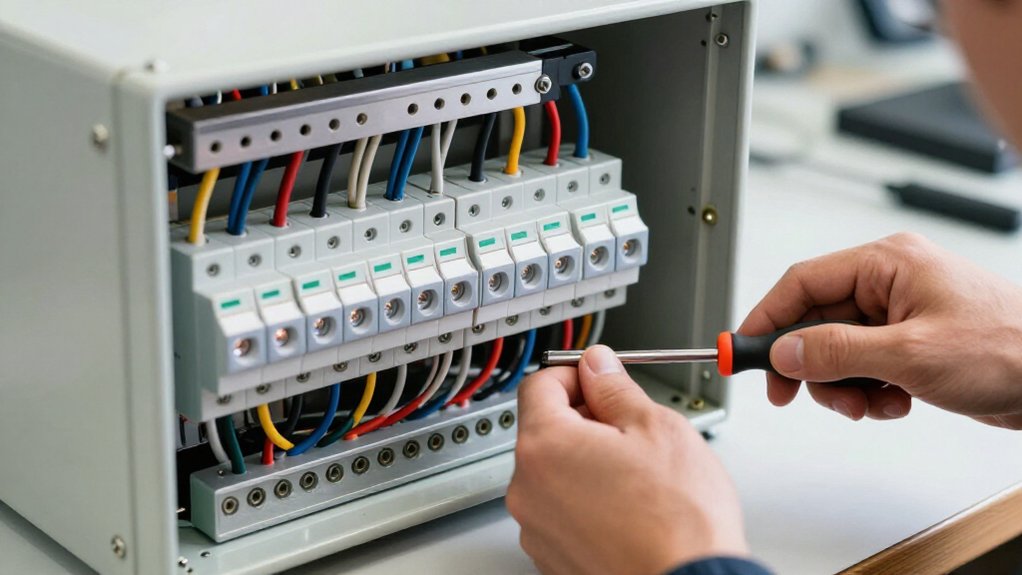
Add each light’s wattage per circuit and divide by system voltage to estimate current; at 12.8 volts, 100 watts draws about 7.8 amps.
Choose a fuse above normal draw but below wire capacity, using 125% of continuous current, and fuse each circuit separately.
Isolate the battery, route wires through grommets, and connect returns to a ground bus.
Feed the panel through a fuse.
Verify operation; more checks protect your wiring.
Circuit Load and Fuse Sizing
Because fuse sizing starts with the load, add the wattage of all lights on each circuit and calculate current with I = P / V; at 12.8 V, a 100 W light bar draws about 7.8 A. Choose a fuse above normal draw but below the wire’s capacity.
A common starting point is 125% of continuous current: an 8 A load may need a 10 A or 15 A fuse, depending on lamp inrush and manufacturer guidance. Give each circuit its own fuse at the fuse block. Use a higher rating for higher-wattage zones, such as a front light bar, and fuse off-road lights separately so one fault won’t disable other lamps.
For long runs, use heavier-gauge wire to limit voltage drop, which can dim lights or overheat a relay. Verify the fuse protects the wire.
Battery Isolation and Bench Setup
Before bench work, isolate the vehicle’s electrical system: switch off the battery isolator or remove the negative terminal, then use a multimeter to confirm power is absent at the switch and relay outputs. On the bench, use a regulated supply set to vehicle voltage, typically 12 or 24 volts, and planned fuse ratings.
- Check the feed side for expected battery voltage; confirm switch and relay outputs remain dead before touching terminals.
- Connect a fused resistor or bulb sized to each light’s amp draw to test relay action, voltage drop, and fuse behavior.
- Use one ground bus for relay and fixture returns; verify end-to-end continuity with your multimeter.
- Keep leads secure and current-limited; stop immediately if wiring heats, a fuse opens, or readings differ from plan.
Step 1: Route Wires Through Grommets
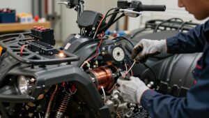
Route every switch-panel circuit through a firewall grommet where it enters the cabin to protect insulation from sharp metal edges. Confirm the wire sits centered in the grommet and isn’t pinched when you tighten it. Inspect both sides for clearance from hot exhaust surfaces and moving mechanisms before securing the run.
Sleeve wire from grommet to panel and from panel to light zones in corrugated loom or braided sleeving. Sleeving adds abrasion protection where vibration can make cables rub. Tie loomed runs to frame rails or dash structure; keep them clear of moving parts, prevent sag, and don’t pull the grommet.
Leave service slack near the panel before final tying so you can remove it without straining wires or the grommet. Check exhaust and mechanism clearance again.
Step 2: Install the Main Ground Bus
With the wire runs protected and secured, install a main ground bus inside the switch-panel system and connect every circuit ground to it rather than daisy-chaining grounds.
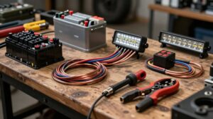
Mount the bus on a surface away from switched-hot and relay-output terminals. Keep ground conductors with the low-current control wiring; don’t route them through fuse blocks. Fit each wire with a properly sized ring terminal, using a crimp tool, then tighten and secure connections against vibration.
Bond the bus to a battery/chassis ground with a dedicated strap or wire sized for the installation. Check continuity from the bus to it with a multimeter; reading should be near zero ohms.
Before powering the panel, test each light circuit’s ground continuity and confirm no switched-hot conductor is shorted to the bus.
Step 3: Connect Panel Power Feed
Connect the panel’s main power feed directly to battery positive through a correctly sized fuse or breaker, using a short, heavy-gauge cable to limit voltage drop. Fit a ring terminal to the battery-positive stud, and crimp it with the correct die so vibration won’t loosen the connection. Run a fused feed to the panel’s input/main terminal; don’t route it through a switch contact.
The protected bus can supply circuit outputs. Ground the panel with a ground strap to a chassis point, using sized wire and ring terminals for a low-resistance return path. Use a multimeter to confirm continuous battery-positive voltage at the panel input and check ground resistance; aim for 0.2–0.5 Ω. Keep cables away from heat, sharp edges, and moving parts, and protect exposed runs with loom.
Step 4: Connect Switches to Relays
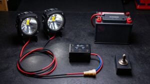
For each lighting circuit, use a relay so the switch carries only the coil’s low current while the contacts handle the lights’ higher current. Connect the relay’s trigger input to that switch’s output, and route the coil return to battery negative for a testable control path. Route the load side from a fused battery positive feed directly to the light’s positive wire.
Keep this high-current path separate from switch wiring.
Before crimping, confirm the coil and contact polarity and ratings match your setup. A 12-volt coil is common, but size contacts for your circuit’s amperage. With power off, use a multimeter to check continuity and voltage at the terminals. Correct any miswiring before you energize the lights.
Testing helps verify your control and load paths.
Step 5: Add Weatherproof Cable Labels
Once the relay and load wiring is in place, label every cable run entering the switch panel so you can trace circuits without guessing. Use a label maker or heat-resistant marker to create weatherproof IDs for every run. Include circuit name, switch position, known wire gauge, and fuse rating; for example, “LT BAR – FUSED 15A POS 1.”
Place a matching label at both ends—at the panel pigtail and near the destination light or relay. Add another label on long runs so you can identify conductors along the route. Cover labels with clear heat-shrink tubing or use UV-rated cable tags to resist moisture, dirt, and abrasion. Keep wording and numbering consistent with your circuit map to prevent swapped circuits during troubleshooting or future additions.
Step 6: Torque Terminal Screws to Spec
Tighten each terminal screw to the manufacturer’s specified torque using a calibrated torque screwdriver; check the switch or panel label or manual, since small terminals often require about 1.0–2.0 Nm. Don’t rely on “feel-tightening.” Overtightening can strip threads or deform the terminal; undertightening can leave insufficient clamp force, raising resistance and heat under load.
Before tightening, select the correct lug or ring terminal size, and seat the conductor fully beneath the screw or clamp. Apply the specified torque smoothly, then stop; don’t add extra force as a precaution.
After torquing, gently tug each wire by hand to verify it’s secure, without pulling or disturbing the strands. Use the tool’s range and calibration status specified by its manufacturer. Resolve any movement before energizing.
Confirm Each Light Illuminates
Before energizing, verify continuity from the fuse block or relay load wire to each light’s positive lead, then check that its ground return has low, consistent resistance to the chassis ground point. With wiring insulated, test one circuit at a time from the switch panel. Set your multimeter to DC volts; with its switch ON, confirm battery voltage at the relay output and light feed. If the light stays dark, switch off and recheck its fuse, connections, switch assignment, and ground.
Don’t bypass a fuse or touch exposed conductors. After each light illuminates, turn it off before testing the next zone. Only when all lights pass individually should you switch multiple zones ON together to confirm correct circuit mapping. Keep hands clear during testing.
Inspect for Voltage Drop
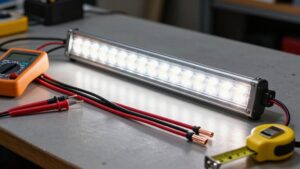
With the lights on, use a multimeter set to DC volts to measure voltage at the switch panel, then at each light’s input under load; compare readings to spot excessive drop, especially on high-current circuits such as front light bars, where long runs or undersized wire can reduce voltage.
| Check | Method | Meaning |
|---|---|---|
| Supply | Compare panel and lamp volts | Large gap signals resistance |
| Ground | Measure light ground to battery negative under load | Above near-zero means ground-path drop |
| Remedy | Check fuse contacts; fit correct gauge, shorten run, secure crimps | Retest before rewrapping harness |
Keep probes insulated, avoid shorts, and don’t disconnect the load during testing.
If the lamp voltage remains low, correct the cause before operating it.
Inspect Terminals for Corrosion Monthly
After confirming voltage drop, inspect the switch panel and relay or fuse area monthly for terminal corrosion. Pull each cover and visually check every terminal, post, and ring-lug contact for white or green deposits, rust, or blistering. Look nearby for dampness, condensation residue, or water trails along the harness; moisture trapped at a connection often drives corrosion.
With power isolated, check terminal tightness and seating. Use a multimeter to compare resistance with earlier readings; a noticeable increase can indicate corrosion and heating. Don’t probe energized connections unless you’re qualified and using precautions.
If you find corrosion, clean contacts to bright metal, dry them fully, and retorque to the manufacturer’s specification. Then verify voltage at the load side and retest circuit operation.
Conclusion
Before you close the panel, verify every fuse matches its circuit and wire rating. Keep the battery isolated while you correct loose connections, then reconnect it only when the wiring is secure. Switch on each light and confirm it illuminates.
Measure voltage drop under load; investigate excessive loss before relying on the system. Inspect terminals monthly for corrosion, heat, or looseness. If readings or wiring seem uncertain, stop and consult a qualified electrician before use.