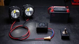
How to Wire a Pre-Wired Rocker Switch: Pin Layout and Backlight
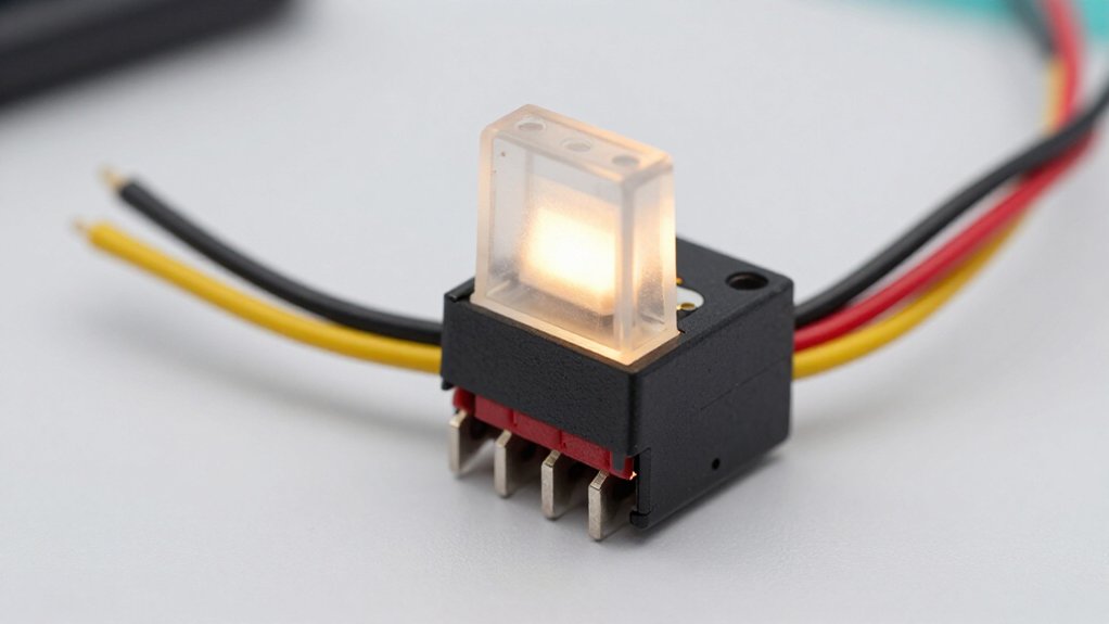
Before wiring a pre-wired rocker, check its rear diagram; colors alone don’t confirm pin functions.
Pin 2 takes fused 12-volt power in, and pin 3 sends switched power to an accessory or relay trigger.
Connect pin 6 to dash illumination and pin 7 to LED ground; pin 8 may share that ground internally.
Mount with clearance and secure connections.
Test the lower backlight with dash lights on and upper indicator with the rocker on.
If it flickers, check feed stability and ground continuity.
Pin Layout and Backlight
Before wiring a pre-wired rocker switch, identify the illumination terminals separately from the main switch circuit.
In a five-pin layout, the switch contacts and LED circuit serve distinct functions. Pin 2 is power in; Pin 3 sends power out to an accessory or relay trigger when you flip the rocker on. Pin 7 provides LED ground for both indicators.
Connect Pin 6, dash light power, to the vehicle illumination or dimmer circuit so the lower backlight follows the dash lights. Pin 8 carries the upper indicator’s ground path; you typically don’t need an external ground wire because the switch links it internally to Pin 7.
Before mounting, test function: with dash power on, the lower light should glow; with the rocker on, the upper indicator should illuminate while the accessory circuit is powered.
Inspect the Switch Wiring
With the pin layout identified, inspect the pre-wired switch before connecting power: check its rear label or diagram to confirm the Power (IN), Load (OUT), and separate backlight pins, then verify each lead’s insulation, gauge, and terminal seating.
Before applying battery power, trace and test the harness:
- Confirm factory lead colors match the pin notes; don’t rely on color alone to identify a circuit.
- Inspect each lead for the specified gauge, intact insulation, and terminals fully seated at rear connector or solder points.
- With power disconnected, use a multimeter’s continuity mode to identify shared grounds or separate backlight-power leads; compare results with the diagram as specified.
- Trace LED pins to the dash/headlight illumination feed, ensuring they’re independent of the switched load path before connecting battery power carefully.
Step 1: Mount the Switch Panel
Choose a rigid mounting location with enough clearance behind the panel for the pre-wired leads, and size the cutout and mounting depth to fit the switch bezel flush without pinching the backlight wires. Check the switch’s specified dimensions before cutting, and confirm the bezel seats evenly without forcing the body. Feed the harness through the opening with a suitable grommet or strain relief to protect insulation from sharp edges and prevent pinching as you tighten the hardware.
Before final tightening, temporarily power the system and verify that the panel backlight illuminates as expected. Watch for flickering or uneven illumination, which may indicate a trapped or strained wire. Disconnect power before securing the panel hardware permanently. Tighten it evenly, and recheck that the switch remains flush and the harness moves freely without pulling on its connections.
Step 2: Connect the Ground Lead
Once the panel is secure, identify the backlight ground lead from the terminal marked GND or the LED ground pin number shown on the switch’s rear. Connect it to a clean, bare-metal chassis point or factory ground bus, giving the backlight a stable reference.
If the switch has separate LED ground pins, such as Pin 7, route every required LED ground connection to that pin exactly as the rear pinout specifies. Use wire gauge suited to the LED current path, and make a secure crimp or soldered joint; a high-resistance connection can make the backlight dim or flicker.
Before applying power, use a multimeter to check continuity between the LED ground pin and battery negative. Keep power off while you test.
Step 3: Connect the Load Wire
After confirming the switch’s pinout, connect the load’s positive (+) wire to the main circuit’s load OUT pin, not a backlight pin, so the accessory receives power only when the switch is ON. Use the main switch contacts, typically the Power IN/Power OUT path, and keep the dash-light and LED-ground pins reserved for illumination.
For a high-current accessory such as a light bar or pump, don’t carry its full current through the rocker; connect load OUT to a relay-coil trigger, such as terminal 86, and let the relay switch the load current. Check that the switch’s DC current rating exceeds the load’s draw before you finalize this connection. Check polarity: load OUT feeds the load’s positive (+) terminal, and ground connects to its negative (+).
Step 4: Connect Fused Power Lead
Connect the fused 12V+ lead to the switch’s Power IN pin, commonly Pin 2 on 5- or 7-pin illuminated rocker switches. Disconnect the battery before wiring, then place an in-line fuse near the power source. Size the fuse to protect the wire and suit the load; don’t install a rating above what the circuit requires.
Confirm the lead supplies switched-compatible 12V power to Power IN, while Power OUT, Pin 3, feeds the accessory or relay trigger when the switch closes. Secure the wire at the pin with a crimp or solder joint. Route it away from heat and moving parts to prevent damage or intermittent operation.
Before restoring power, keep the battery disconnected and use multimeter to verify continuity from the fused lead to Power IN.
Step 5: Test the Backlight Polarity
Before applying power, identify the backlight pins from the numbers printed on the switch’s rear; they commonly include a dash-light positive input and two ground or return pins.
Keep the main load circuit disconnected. Connect only the backlight: feed its dash-light positive pin with fused 12V, or the specified voltage, and connect a return pin to battery negative or chassis ground. Use a fuse appropriate to the circuit, and avoid touching exposed conductors while energized.
If dark, disconnect power and swap only the backlight return; with separate inputs, reverse those leads. LEDs are polarity-sensitive. Check illumination and current with a meter; draw should stay well under 1A.
Reconnect main power and load. The backlight should follow the dash/headlight trigger, not necessarily rocker position alone.
Step 6: Route Wires Away From Sharp Edges
Route each lead with clearance from the switch’s metal tabs and panel back, keeping slack clear of mounting screws so it can’t get pinched. At the cutout, protect any lead passing within a few centimeters of the edge with split loom, heat-shrink tubing, or a suitable grommet. Before you tighten the switch or panel, inspect the full route for contact with sharp sheet-metal edges and drilling or cutting burrs.
Smooth or deburr the area before installation; don’t rely on insulation alone to withstand vibration.
Keep the backlight leads, typically connected to dedicated dash or LED pins, apart from high-current load wires so they can’t chafe against one another. Secure both groups with zip ties or adhesive mounts, leaving enough service slack without letting wires shift as you push the switch into place. Recheck clearance around tabs, edges, and fasteners after seating the assembly, before completing the panel fastening.
Verify Illumination With Headlights on
With the vehicle ignition on, switch on the headlights or dash lights and check that the rocker’s backlight receives about 12 V at its dash-light pin only while the lights are on. Keep the main rocker function OFF; the backlight should still illuminate, showing that its circuit is separate from the switched load. If it stays dark, use a multimeter to measure the illumination “+” feed at the switch: expect about 12 V with the headlights on and about 0 V with them off. Avoid probing adjacent terminals or shorting the pins; secure the meter leads and keep clear of moving parts.
With the headlights still on, toggle the rocker ON and confirm the upper indicator changes state, such as its icon LED lighting. The backlight should remain powered independently. Turn the ignition and lights off after testing, then refit any trim you removed. Follow the vehicle wiring diagram and use insulated probes for the measurement.
Diagnose a Flickering Backlight
A flickering backlight often points to a poor LED ground, such as a loose Pin 7 connection, or an unstable illumination feed, commonly Pin 6. Use these checks to isolate the fault:
| Check | What to verify |
|---|---|
| Ground | Pin 7 and chassis/negative-bus continuity |
| Feed | Pin 6 stays steady; avoid PWM-dimmed or overloaded circuits |
| Mapping | Keep LED/ACC separate from main Power IN |
With the lights on, measure voltage at the backlight Power IN pin using a multimeter; it should remain near 12–13.8V DC. Wiggle the harness gently and watch for drops that reveal an intermittent crimp or broken pre-wire strand.
Disconnect power before handling any conductors safely. Check spade or solder joints and grounds for looseness or corrosion. If voltage fluctuates, isolate the circuit and repair the fault before continued use.
Secure Connections Against Corrosion
To protect the backlight wiring from corrosion, use marine- or automotive-grade heat-shrink connectors sized for the wire gauge, and crimp them securely to limit moisture wicking into the joint. After wiring the backlight circuit, including the dash-light feed and LED grounds shown on your switch’s pin map, apply dielectric grease to metal.
Cover each connection with heat-shrink. Route wires away from exhaust and engine heat and sharp edges; add loom, and fit grommets where the harness passes through the panel. Tighten GND and power terminals to the manufacturer’s torque specification, then recheck them after the dry run.
Before final assembly, use a multimeter to confirm near-zero continuity and voltage drop under load. Higher resistance can cause heat buildup and speed corrosion.
Conclusion
Inspect the pre-wired switch’s pin layout before you connect anything; wire colors and terminals can vary. Mount the panel securely, attach the ground and load leads to the correct circuits, and keep wiring clear of sharp edges and moving parts.
Protect connections against moisture and corrosion. With the headlights on, verify that the backlight works as intended. If it flickers, switch off power and check the ground and connections. Don’t energize the circuit until you’ve confirmed every connection is secure.