
How to Wire a Light Bar on a 4Runner (Clean Firewall Routing)
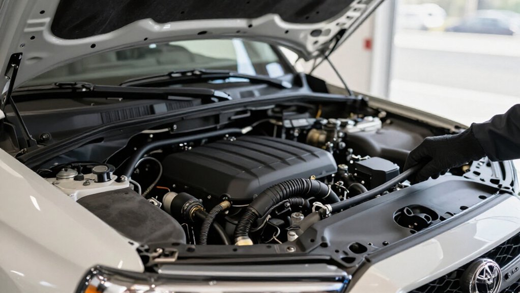
Disconnect your 4Runner’s negative battery terminal; gather a fused kit, loom, connectors, and eye protection.
Tape painted fender edges before routing.
Feed the harness through an unused factory firewall grommet, protect its lip, and press it flush to seal.
Connect fused power and a ground as the kit specifies.
Secure leads away from heat, sharp edges, fans, and moving parts.
Check beam aim, test relay clicking with a multimeter, and inspect for chafing before proceeding.
Firewall Grommet Access
Before routing the light-bar harness, remove the driver-side trim panels and locate a factory firewall grommet with enough slack for the cable. Use a flathead or plastic trim tool to expose the grommet without damaging its rubber lip. Check behind the opening for clearance; make sure the harness won’t contact sharp sheet metal edges or connectors. Feed the harness through the opening and center it within the rubber so the grommet continues to seal against water intrusion.
If no suitable pass-through exists, use a spare grommet opening or a dedicated grommet, so the cable never rests on bare metal. Re-seat the grommet in the firewall. Give the harness a light tug to confirm it’s secured in place and won’t shift when the firewall flexes.
Gather Wiring Supplies and PPE
Gather the wiring kit and safety gear before routing the harness: confirm it includes a fused power lead, relay or control module, ground wire, and switch or trigger wiring.
- Match the power-lead gauge, typically 10–14 AWG, to your bar’s current, and verify the fuse rating against kit instructions.
- Pack heat-shrink butt connectors, waterproof inline connectors, split loom or braided sleeve, and ample zip ties.
- Wear safety glasses for debris, cut-resistant gloves when trimming cable, and nitrile gloves around adhesives or corrosion protectants.
- Set out Phillips and flathead screwdrivers, a plastic trim tool, and crimping pliers if connectors need crimping.
- Keep supplies within reach and inspect each connector before use; damaged insulation or loose crimps can compromise protection.
Route the harness along factory paths securely.
Step 1: Protect Painted Fender Edges
Along the fender, protect the paint before routing the harness: cover the edge with painter’s tape or a foam fender cover, and feed the wire through factory gaps or grommets rather than over sharp metal. Add split-loom where the harness passes close to the fender opening. Use plastic trim clips or adhesive mounts, not the fender lip, and keep cable 1–2 cm from painted edges where possible.
At zip-tie points, fit a rubber insulator or use a wide mounting base so vibration and heat cycles won’t press the tie into the finish. After securing the harness, turn the steering through its full range and flex the suspension; check for rubbing. Reposition contact points and retape any exposed edge where paint could touch the loom.
Step 2: Disconnect Negative Battery Terminal
With the harness route planned, switch off the 4Runner and locate its battery. Choose a socket that fits the negative (–) terminal clamp nut, then loosen it without contacting the positive terminal or nearby metal with your tool. Lift the negative cable off the battery post to disconnect vehicle power.
Keep the loose cable secured away from the battery post and any metal bodywork while you work. After disconnecting the terminal, pause so the ECU and other vehicle modules can complete their normal power-down sequence before you connect the light bar harness.
Expect minor resets, such as clock or radio presets, if your 4Runner retains settings. When installation is complete, reinstall the negative clamp, tighten it securely, and verify solid contact before powering the lights.
Step 3: Feed Harness Through Grommet
Once the battery’s disconnected, locate the factory firewall grommet near the steering column or fuse box. Choose an unused rubber pass-through so the opening remains sealed against water and fumes.
From the engine bay side, guide the light bar’s main harness through with fish tape or stiff wire. Feed it carefully until the connector ends reach the cabin. Before pulling the bundle fully through, inspect the grommet lip. Confirm it grips the wires without pinching or cutting insulation.
Inside, pull only enough slack for your planned route. Secure the harness with zip ties so it can’t touch sharp metal edges or moving parts near the dash. Apply a small amount of suitable grommet sealant or silicone around the pass-through to preserve a weather-tight seal.
Step 4: Connect Lightbar Power and Ground
Keep the battery disconnected while you route the harness’s red power wire from the firewall-mounted distribution point or fused lead toward the battery, and connect the black ground wire to a clean, bare-metal factory ground stud or firewall point. Confirm the power lead carries an inline fuse rated to the lightbar manufacturer’s recommendation; don’t substitute a higher rating. Scrape paint from the chosen grounding surface if needed, then secure the lug tightly to maintain a low-resistance connection.
Tuck both wires behind existing trim and secure them with zip ties or adhesive mounts, clear of moving parts, radiator fans, and exhaust heat. Before making the final battery connection, use a multimeter: ground should measure about 0–1 Ω to battery negative, while switched power should read zero with the switch off and battery voltage when on. Recheck ground-lug tightness and fuse seating; a poor ground can cause dim output or intermittent switching. Inspect routing for pinching, sharp edges, and strain before you energize the circuit.
Step 5: Seal Firewall Grommet
Make a tight slit in the firewall grommet with a sharp razor, then feed the harness through with the connector inside the cabin and the wire seated snugly in the rubber. Keep the slit no wider than the loom to preserve the seal. Avoid nicking wiring or tearing the rubber.
After routing, apply dielectric grease or a thin bead of RTV silicone at the wire-entry point on the engine-bay side; don’t use both. Press the grommet into the firewall until it sits flush all around, leaving no gap for water to track along the harness. Under the dash, leave a service loop and secure the harness near the grommet with a clip or zip tie. This reduces movement that could work the grommet loose.
Step 6: Label and Bundle the Leads
With the firewall grommet sealed, label each light-bar harness lead—power (+), ground (−), switch/signal, and any auxiliary wire—with painter’s tape before the firewall pass in Step 13.
Bundle the extension harness into 6–12-inch sections, using zip ties only at mounting points. Leave connectors and the light-bar bracket area untied to avoid stressing strain-sensitive plugs. Route bundles along the bumper/bracket top, then keep the firewall segment straight to reduce slack and tangling. Use the provided adhesive mounts at several spots to hold the harness down and prevent sagging near the grommet. Keep the switch/signal lead a few inches from the power lead within each bundle; separation minimizes noise and simplifies final connections. Check every label before making cabin-side connections.
Verify Lightbar Beam Aim
Before aiming the lightbar, park on level ground, set the tire pressure correctly, and measure the height of the bar above the ground. Mark that same height on a wall 25 ft (7.6 m) ahead. Use a level string or laser to establish a straight reference line, then check the beam cutoff centerline falls about 1–2 in (25–50 mm) below the mark. Aim the brightest center parallel to the road or a few degrees downward; this helps limit glare.
Adjust the mounting hardware evenly, in increments, keeping the pattern symmetrical left to right and up to down. Tighten the bracket fasteners with a T20 Torx if your kit uses one, then recheck aim because tightening can shift it. In darkness, test with high beams on and off. Confirm the pattern stays centered and doesn’t shine excessively above vehicle height or into a driver’s line of sight.
Diagnose Relay Clicking Noise
When the relay clicks repeatedly with the lightbar switch on, its coil is likely losing power or the contact circuit is failing. Park safely and avoid probing exposed live terminals. With a multimeter, measure battery voltage at the relay’s power input while clicking; below about 12.0–12.5 V suggests a weak splice, undersized wire, or poor ground. Then measure voltage drop from relay ground to battery negative; above 0.2 V indicates excess resistance.
| Check | Result | Next step |
|---|---|---|
| Supply voltage | Low | Check splice/wire |
| Ground drop | Over 0.2 V | Correct ground |
| Unplugged bar | Clicking stops | Check bar connector |
If clicking continues with the lightbar unplugged, suspect the relay control circuit or relay. If it stops, suspect the bar circuit; carefully inspect its connector and wiring for an intermittent short.
Inspect Harness for Chafing
Once the relay circuit checks out, inspect the light-bar harness for chafing before routing it further. With the vehicle parked safely, examine the full wire run, especially where it crosses brackets and follows the bumper’s top edge. Look for cuts, fraying, or worn insulation; repair or replace damaged sections before installation.
Check pinch points between the grille support or active-shutter brackets and bumper cover. Confirm the loom has clearance and won’t rub during suspension travel or steering turns. At firewall penetrations, verify each grommet is seated or a protective sleeve shields the wire from the hole’s edge.
Inspect zip ties: leave them snug, not tight enough to compress the sheath. Gently tug and flex the harness by hand to reveal movement toward contact points. Re-secure it, then continue routing.
Conclusion
You’ve routed the harness through the firewall and checked the beam, relay, and wiring. Before you call the job done, confirm every connection is secure, the fuse is correctly rated, and the cable can’t chafe on metal or moving parts.
Reconnect the negative terminal last, then test the light bar with the vehicle stationary. If the relay clicks repeatedly, wiring heats up, or the beam aim is unsafe, switch the system off and correct the fault before driving.