
Wireless vs Wired Switch Panel: Reliability, Install and Control
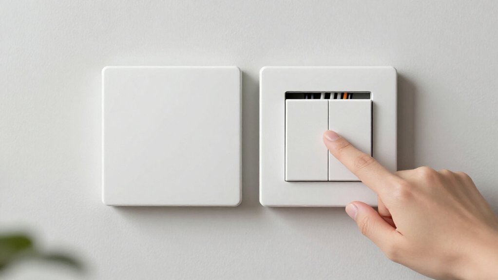
A wired switch panel gives you direct, conductor-based control, avoiding RF range and interference limits, but it needs suitable wiring and may require a neutral for its electronics.
A wireless panel sends radio commands to a paired receiver at the fixture or junction, so you can place the control where it’s convenient and avoid opening finished walls.
Its reliability depends on distance, obstructions, and interference; receiver compatibility governs dimming.
More details clarify installation and code trade-offs.
Neutral Wire Requirements
For a wired smart switch, neutral-wire requirements depend on the device’s design: many models need the neutral conductor to power their electronics without drawing current through the load. Check your switch box before buying: if it contains only line and switched-leg conductors, a neutral-required model may fail or force replacement. Choose a model explicitly rated for neutral-less installation when no neutral is present.
Some battery-free or wireless receiver-based systems avoid this constraint because their receiver connects at the fixture or junction box.
| Situation | What it means |
|---|---|
| Neutral present | Peace of mind |
| Neutral absent | Risk of failure |
Confirm conductor identification against the manufacturer’s diagram and local electrical code; miswiring can stop operation and create unsafe conditions, so don’t infer neutral availability from wire color alone.
Switch Panel Signal Paths
A wired switch panel sends commands through a physical conductor to the control device, which switches power to the light; this direct path provides consistent, low-latency control. With a wired system, you connect the panel to the control device and that device to the lighting load. The conductor carries the command; the device switches the load.
A wireless panel sends a radio command to a receiver, which you mount at the fixture or junction box and hardwire to line voltage and the light. Pair the switch with that receiver before operation. In energy-harvesting designs, including 902 MHz EnOcean-style systems, pressing the switch creates kinetic energy for transmitting the message. You eliminate the command conductor, but retain the wired power path from receiver to load.
Signal Range and Obstructions
Although 902 MHz EnOcean-style panels can reach up to about 150 ft in indoor conditions, some are rated for roughly 100 ft, and actual range depends on the radio path.
At those distances, signal strength can fall as you move controls farther from the receiver or control module. That loss may make commands inconsistent.
Vehicle body panels, thick metal, engine compartments, and dense interior framing can absorb or block RF energy, reducing coverage below open-space estimates.
Other electronics and RF interference can further degrade performance, so two rigs with similar range ratings may behave differently in cluttered or signal-heavy locations. Unlike a hardwired circuit, each wireless action depends on a dependable radio path. Account for distance, barriers, and interference when evaluating whether the link will remain reliable throughout operation.
Wall-Plate Placement Flexibility
Signal range sets the practical limits, but wireless controls give you more freedom to choose a wall-plate location because you don’t need to run control wires back to a central panel. Pair the switch with a receiver mounted at the fixture or junction point. This keeps the wired connection there while you place the plate where control is convenient.
An energy-harvesting EnOcean-style switch attaches with adhesive or screws, so you don’t need an electrical-box cut-in. Relocation is simpler than rewiring; press the receiver’s learn button, then use the switch’s pairing sequence, such as three presses of its top button. After moving the plate, you’ll need to pair it again. Keep it within range: indoor reach may approach 150 feet at 902 MHz.
Dimmer and Load Support
Even when a wireless switch pairs reliably, the receiver must match both the load and its dimming method.
With an EnOcean-style system, you connect line voltage and the lighting load at the receiver, typically in the fixture or junction box. That makes load support depend primarily on the receiver, not the battery-free switch.
For LEDs, check that the receiver’s dimmer supports the driver’s dimming method and control style; fixture type alone doesn’t confirm compatibility. A mismatch can cause flicker or reduce dimming performance. You still need to verify the specified load type and wiring requirements before installation.
A wireless link rated for up to about 150 feet indoors at 902 MHz doesn’t resolve electrical incompatibility or guarantee smooth dimming under the connected load.
Energy-Harvesting Switch Operation
Pressing an energy-harvesting switch converts the press’s kinetic energy into enough power to send a lighting-control signal over EnOcean’s 902 MHz wireless link, so the switch needs no battery. Each press supplies the energy for transmission, eliminating battery replacement and maintenance.
You can place the switch where wiring would be difficult, while the receiver handles the lighting load. Indoors, expect a range of up to about 150 feet; specifications may state up to 100 feet indoors. Performance depends on the room and signal path, so assess placement against the receiver’s location.
A clear line-of-sight path supports dependable communication, but interior placement can work without direct visibility when conditions permit. Because the switch generates its own transmission energy, you avoid battery service and replacement cycles throughout use.
Panel Pairing Security
To bind a wireless panel to its lighting load, pair it at the receiver only after confirming the wiring is safe and the panel’s mounting position is set. Keep the receiver de-energized during installation; restore power for normal operation. Its wiring connects it to the intended lighting load.
At the receiver, press “learn,” then press the panel’s top button three times. Pairing typically takes about 30 seconds and assigns control over the 902 MHz EnOcean RF link; you don’t need Wi-Fi or Bluetooth. This deliberate sequence, rather than continuous transmission, reduces accidental enrollment during ordinary use. Pair only when the intended switch is within the pairing window. If pairing doesn’t complete, repeat the sequence and verify that the panel controls the intended load securely.
Upfront and Long-Term Costs
You’ll typically pay more upfront for wireless switches, but avoiding extensive wiring can reduce total installation costs. Compare the receiver-and-switch cost at each location with wired labor and infrastructure access.
Over time, energy-harvesting switches can also eliminate battery and maintenance expenses.
Initial Installation Costs
Although wireless kits often cost more per switch, they can lower total retrofit costs by avoiding extensive wiring runs to new control locations. When you add switches or lights, compare kit prices with the labor and materials required to route dash or hood wires. Wireless receivers mount at or near fixtures, so you need only power-to-load wiring at those points.
That arrangement can simplify installation and reduce upfront routing complexity, especially when controls sit far from loads. Wired toggles may cost less individually and use fewer components, but each added control location can require a run. If you’re already pulling circuits for other work, wired installation may add little incremental effort. Your cost comparison should as a result include equipment, labor, and routing.
Long-Term Operating Expenses
The initial price is only part of a switch panel’s lifetime cost. Wireless panels often cost more upfront than wired toggles, but you can lower retrofit installation costs by avoiding dozens of wires routed through the cabin or dash.
Battery-free, energy-harvesting switches generate power when you press them, so you won’t replace batteries; that reduces ongoing maintenance. However, each wireless lighting location needs a receiver wired to line voltage and the load, shifting expense to per-fixture installation.
Wired setups may cost less in materials and labor when new wiring is already planned, but later changes can require rewiring. Your lifetime total depends on whether avoided wire-routing complexity outweighs receiver work, future lighting expansion, and maintenance. Evaluate these costs against your expected system changes carefully.
Retrofits Without Wall Damage
If you can’t cut or patch your walls, a wireless switch can preserve existing finishes by placing its receiver at the fixture or junction box. You can mount the energy-harvesting switch with adhesive or screws and pair it in about 30 seconds, limiting disruption during installation.
Check local code requirements, since electrical work may remain limited to the receiver location.
Preserve Existing Walls
When you retrofit lighting in a finished or protected space, wireless switches can preserve the walls because the receiver mounts at the fixture or junction box, with no switch-side box or wall cutting. An energy-harvesting switch sends its command without new control wiring through plaster or other protected surfaces. To pair it, press the receiver’s learn button, then press the switch’s top button three times; the sequence takes about 30 seconds.
You’ll typically complete one location in 10–15 minutes, including receiver wiring at the light’s power source. That wiring still connects line voltage to the lighting load, so assess fixture access and electrical conditions before installation. Once paired, the switch needs no battery replacement.
If you expand control later, you can plug additional harnesses into the pigtails, adding functions without altering the existing wall assembly. This approach suits occupied renovations where preserving finished surfaces and limiting disturbance matter during active work in the space, with minimal disruption.
Avoid Cutting And Patching
For retrofits, wireless switches avoid cutting and patching by pairing battery-free, energy-harvesting EnOcean switches with small receiver modules at the fixtures or junction boxes.
You wire each receiver at the line-voltage power/load location, connecting it to the lighting load instead of routing switch conductors through walls. This architecture keeps surfaces intact and reduces wiring complexity.
When you add a light, wire its receiver and connect a harness/pigtail for the controller; you typically won’t reopen walls to reroute switch conductors. Pair each switch by pressing the receiver’s learn button, then pressing the switch’s top button three times; pairing takes about 30 seconds per switch. Mount the switch with adhesive backing or screws, without an electrical box or cutting the wall. Therefore, you avoid patching.
Install With Minimal Disruption
Because the receiver mounts at each fixture or junction box, you can add wireless control without cutting walls or pulling cable through existing cavities.
You install the receiver where the line and load conductors are available. Turn off power before connecting it; allow about 10–15 minutes per light location. Then pair locally: press the receiver’s learn button, then press the switch’s top button three times. The sequence takes 30 seconds.
Because the switch harvests energy each press, it needs no battery wiring or cable run to the panel. This reduces retrofit work during a typical installation compared with installing hardwired switches and pulling cable through walls or dash areas.
If you expand control later, wire another receiver at the new fixture and pair a new switch, rather than reworking the panel circuitry.
Check Local Electrical Codes
Before choosing a wireless or wired switch panel, verify local electrical codes and permit requirements with your authority having jurisdiction (AHJ). Wireless systems may qualify as control devices, with wiring concentrated at the receiver; however, you must verify how your AHJ classifies them. For retrofits, confirm line-voltage receiver switching is permitted, and check wiring methods, junction-box rules, and receiver-site inspection criteria.
- Confirm whether permits are required before installation.
- Check energy-harvesting switch wiring, and verify LED loads and drivers match code and manufacturer instructions.
- Determine whether energy standards, including ASHRAE 90.1, IECC, or Title 24, govern your project and controls strategy.
- Ask a licensed electrician to document hardline topology or wireless receiver/load switching for compliance and inspection readiness.
That review should happen before you select equipment, because approval depends on circuit topology, specific loads, and inspection rules, not merely the panel’s wireless or wired interface.
Conclusion
Choose a wired switch panel when you need predictable signaling, direct load control, and don’t mind opening walls to verify neutral wiring and code compliance. Choose wireless when you need flexible placement or a retrofit that avoids wall damage, but check range, obstructions, pairing security, and dimmer compatibility.
Compare upfront hardware and installation with battery or service needs over time. Before you install either system, confirm its signal path and supported loads meet your requirements.