How to Wire Rock Lights Safely: Controller, Fuse and Clean Routing
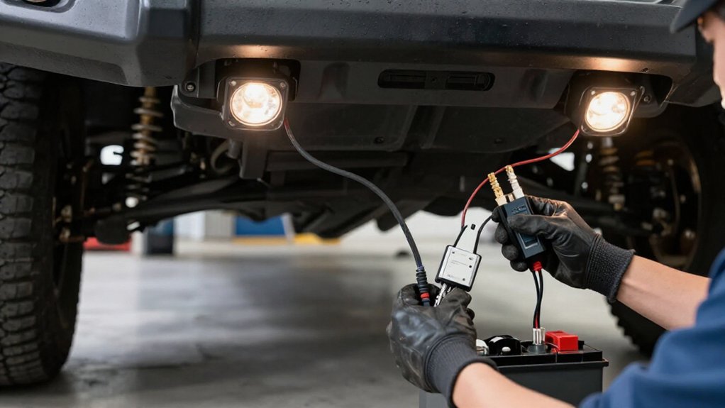
Mount the controller in a dry spot away from heat and moving parts.
Disconnect the battery, then connect red to a 12V source through the kit-rated inline fuse near the battery, and black to chassis ground.
Confirm the controller’s 12V input limit.
Label leads, crimp terminals, seal joints with heat-shrink, and protect routes in loom.
Test each pod evenly before securing wiring; investigate repeated fuse failures.
Next, learn how to check faults and inspect after mud.
Controller and Fuse Placement
Mount the RGBW controller in a dry, protected location, such as inside the cab or near the fuse box, away from water spray, heat, and moving parts. Keep both accessible, and route wires away from heat and moving parts to prevent abrasion.
Connect the red harness lead to a 12V positive source through the kit’s inline fuse or an appropriately rated fuse. Place that fuse close to the positive terminal so a wiring short receives protection before the harness overheats. Connect the black lead to a solid chassis ground.
If your kit includes an AUX trigger input, wire AUX ON to power the controller and AUX OFF to shut it down fully. During testing, also confirm the controller turns off with the switch off.
Check Vehicle Battery Condition
Before wiring, verify that your vehicle has a stable 12V DC system and a healthy battery; most rock-light kits aren’t designed for 24V. Use a multimeter to assess voltage before connecting the controller:
- A fully charged battery typically reads about 12.6V; around 12.0V or higher with the engine off is a useful check.
- With the engine running, confirm steady charging voltage of 13.5 to 14.7V; low or fluctuating readings can cause controller brownouts and intermittent lights.
- Inspect terminals for corrosion and looseness, and watch for slow cranking, dim headlights, or repeated jump starts.
These signs suggest a weak battery or high-resistance connection. Turn on headlights and other accessories, then recheck voltage; excessive sag warrants diagnosis before installation.
A correct fuse can’t compensate for an unstable supply.
Step 1: Label the Wiring Route
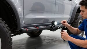
Label each lead before routing it, using clear names such as “Front Left Pod 1,” “Rear Right Pod 2,” “Controller Power +,” and “Controller Ground –.” Add tape flags or printed labels every 12–18 in (30–45 cm) and near each connector, then mark the planned path, bends, and controller entry point on the frame or underbody to keep wiring clear of exhaust heat and moving parts.
Mark the battery feed and fuse location “FUSED 12V BAT + here” so polarity’s unmistakable. Follow the route clear of exhaust heat and moving parts. Check continuity and polarity on each labeled run before tightening mounts. Verify each pod label matches its controller channel and order before final connection. Replace loose or unreadable labels promptly to avoid mix-ups later.
Step 2: Confirm the Controller’s Voltage Limit
Check the controller’s specification for a 12V DC input and confirm its accepted voltage range, including the higher voltage produced by the alternator while the engine runs.
Read the manual or spec sheet for the controller’s maximum input. Some units accept charging voltage up to 14.4V; alternator output can reach 14.7V, so don’t assume a “12V” label guarantees operation. Measure battery voltage with a multimeter: expect 12.6V at rest and 13.8–14.7V with the engine running. Compare readings with the controller’s range before connecting power.
Verify that the controller matches your lights’ voltage and LED protocol; an RGBW controller supports RGBW pods only. If the limit or compatibility is unclear, stop and contact the manufacturer or seller before connecting the red power wire to 12V.
Step 3: Strip and Crimp Wire Ends
Cut each wire to length with a little slack, then strip about 3–5 mm (¼ in) of insulation so only the copper is exposed. Choose a crimp terminal that matches your wire gauge; an oversized barrel may loosen, while an undersized one can damage strands. Avoid nicking copper. Slide heat-shrink tubing onto the wire before crimping, or use a weatherproof heat-shrink butt connector. Insert all strands fully into the barrel; no copper should remain exposed.
Crimp firmly with the tool, compressing the barrel without cutting strands. Give connections a tug; they shouldn’t pull free. Bad crimps cause intermittent rock-light failures. Shrink tubing evenly after crimping to seal out moisture and vibration, and cover exposed metal to prevent shorts.
Step 4: Connect Controller to Battery
Before wiring, mount the RGBW controller in a dry, protected spot near the battery or fuse box, then disconnect the vehicle battery. Connect the controller’s red power wire to a fused 12V positive lead. Attach its black ground wire to clean, unpainted metal chassis ground; remove paint or corrosion at the contact point.
Select a fuse rated for the controller or kit’s current draw so it protects the circuit from shorts and overloads. If you’re using an AUX or toggle-style controller, verify that AUX ON supplies power and AUX OFF cuts it. Secure connections and insulate metal with heat shrink or electrical tape.
Reconnect the battery only after you’ve secured and insulated the wiring. Then confirm the controller powers up before plugging in the pods.
Step 5: Test Voltage at the Battery
With the vehicle battery disconnected from the wiring, set a multimeter to DC volts and measure across the battery’s positive terminal and a known solid ground; expect about 12.6V when fully charged or 12.0, 12.2V when partially discharged. Use the same meter polarity and contact points to verify true supply voltage; a poor ground can produce a misleading reading. Reconnect the battery temporarily only if needed to check voltage while the rock-light circuit draws power.
Watch for a substantial drop, which may indicate loose battery connections. For a 12V DC kit, don’t proceed if voltage is markedly low, such as about 11.5V or less; the controller and LEDs may dim, flicker, or fail. After testing, disconnect the battery again before changing wiring to prevent a short at the controller’s power input or a blown harness fuse. Follow the kit maker’s specified range; investigate abnormal readings before continuing with the circuit switched off for safety.
Step 6: Add Abrasion-Resistant Loom
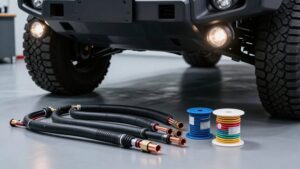
To prevent chafing, cover every wire run exposed to metal, brackets, or the vehicle underside with split-loom tubing or similar abrasion-resistant conduit. Start the loom a few inches before each mounting grommet or entry point, and extend it beyond the full pinch or turn area. Keep the loom snug so vibration can’t slide it off.
At controller-harness terminations, leave loom ends uncut; seal them with heat-shrink tubing or electrical tape to keep water and grit from wicking into the insulation.
Secure loom to factory frame paths with zip ties every 6–12 inches. Don’t overtighten ties; compression can damage insulation. Route covered wires clear of exhaust, moving suspension points, and sharp edges.
After tightening, tug each run lightly to confirm it won’t chafe or loosen later.
Verify Lights Illuminate Evenly
Power the controller and test each rock light pod before permanently securing the wiring. Test all pods individually or simultaneously, confirming every LED illuminates at the same brightness. Set white mode at full brightness, or choose the brightest setting; colorless output makes uneven RGBW performance easier to spot.
Compare beam coverage from each wheel-well pod, front driver, front passenger, rear driver, and rear passenger, on the ground directly below the vehicle. If a pod looks dim or patchy, stop and reseat its connector. Check that its ground connection is clean and solid; don’t attach it to painted metal, since poor grounding can cause brightness differences. Only after brightness matches across all pods, fully secure the harness with zip ties, then cycle-test the lights afterward.
Diagnose Blown Fuses
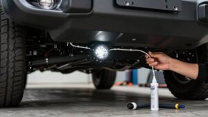
If the fuse blows as soon as you switch the rock lights on, turn the system off and unplug the controller harness from the lights. Check pod connectors for shorts, then trace wires near wheel wells and underbody for pinches. Confirm the inline fuse near the battery matches your kit’s rating; never install a larger fuse to hide a fault. Inspect the ground at unpainted chassis metal and tighten it.
| Check | Likely fault | Next action |
|---|---|---|
| Fuse still blows | Pinched lead | Repair insulation |
| Near-zero resistance | Power-to-ground short | Disconnect battery; locate fault |
| Loose ground | Poor contact | Clean bare metal |
With battery disconnected, measure resistance from controller 12V+ to ground; near-zero readings indicate a short. After repair, secure system, test once, and replace fuse only once. Stop if repeated.
Inspect After Muddy Trail Runs
After a muddy trail run, switch off the rock lights and inspect every pod for cracked lenses, loose mounting hardware, or mud blocking the lens face.
Check wiring for abrasion or pulled loom near frame edges, skid plates, and pinch points. Confirm zip ties and heat-shrink haven’t shifted into steering or moving-suspension areas.
Inspect controller, power, and ground connections for corrosion or moisture, especially at plugs and the fuse area. Reseat any connector that looks lifted. Verify the ground remains solid; flicker or partial outages can signal a poor connection or an unclean metal ground point.
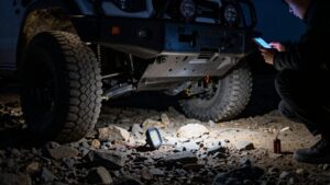
Then test each pod with all lights on. If you have RGBW lights, cycle each color and brightness mode. Watch for individual failures that may appear only under vibration.
Conclusion
Before you power the rock lights, verify the battery is healthy and the controller matches the system’s voltage. Place the controller safely, protect the feed with a fuse near the battery, and label your route. Strip and crimp connections securely, then cover exposed wiring with abrasion-resistant loom.
Test for even illumination and operation. If a fuse blows, don’t replace it until you find the fault. After muddy runs, inspect routing, connections, and protection before driving.