How to Wire a Third Brake Light (Stock Circuit or Aftermarket Pod)
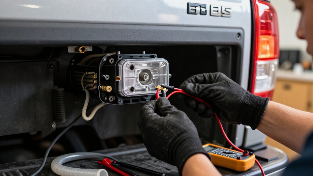
Use a vehicle-specific plug-in kit when available; otherwise attach an aftermarket pod to the confirmed brake-light feed and chassis ground.
Disconnect the negative battery terminal before wiring, then locate the brake wire using vehicle documentation and a DVOM.
Temporarily reattach power to confirm that about 12 volts appears only while the pedal is pressed.
Disconnect again, splice securely, heat-shrink connections, and route wiring away from heat and moving components.
Test and aim the light; proper checks help ensure dependability.
Stock Circuit or Aftermarket Pod
If your pod is designed for a stock-circuit hookup, use the vehicle’s brake-light harness or supplied plug-in connector rather than tapping an unidentified wire. Many kits plug into a four-way connector at the taillight harness junction, often near the left rear corner. For a retrofit, the connector can replace the original brake-light feed and route it to the pod.
Wire the pod’s power lead to the brake line that reads about 12V only when you press the pedal; connect its ground to confirmed chassis ground. Match the feed wire using vehicle-specific documentation; colors can vary by model year. Route and secure the harness away from heat and moving parts, then mount the pod high and centered. With ignition on, have a helper press the brake pedal.
Gather Tools and Materials
Before you begin, choose a third brake light kit made for your vehicle and gather its lamp, harness, and connectors.
Match the kit to your application: a plug-in retrofit should include its pigtail, while an aftermarket pod may need a mounting base, gasket, and hardware. Lay out:
- Wire strippers and cutters/crimpers, plus electrical tape or heat-shrink tubing for insulated, secure splices.
- A 12V test light or DVOM to verify the brake-feed wire reads about 12V only while you press the pedal.
- If drilling, gather a drill-bit and screw set; keep screwdrivers and a ground-point locator handy.
Confirm magnetic kits include a magnet and gasket; magnets won’t hold reliably on aluminum or fiberglass. Choose bits and fasteners that suit the mounting surface and pod design.
Step 1: Disconnect the Negative Battery Terminal
To prevent short circuits and blown fuses, disconnect the negative (–) battery cable before handling any third brake light wiring.
Locate the negative post at your vehicle’s battery. With the correct tool, typically a wrench, loosen the clamp and lift the cable off the post. Don’t pull on the cable itself or let the clamp touch the positive terminal.
Move the disconnected cable aside and secure it so it can’t spring back into contact with the battery. This separation removes live power and reduces accidental short-circuit risk while you’re working. Once isolated, you can access the rear brake-light harness or third brake-light connector without live power.
Keep the negative cable disconnected until all third brake-light wiring and ground connections are fully made and secured. Reconnect it only then.
Step 2: Find the Brake-Light Signal
With the battery still disconnected, locate the brake-light switch on the pedal assembly or the brake-light feed at the rear harness, then identify the wire that carries about 12 volts only while the pedal is pressed.
For testing, reconnect the battery temporarily. Have a helper press and release the pedal. Set a DVOM to DC volts, place its black lead on known chassis ground, and touch the red lead to candidate wires.
The correct wire shows battery voltage only while braking and 0V when released, across several cycles. The CHMSL feed joins the rear lamp harness, near the left rear corner. Check your vehicle’s wiring data and confirm an aftermarket pod’s signal-wire color for your exact year and model. Disconnect power again before wiring.
Step 3: Tap the Brake-Signal Wire
Once you’ve confirmed the signal, locate the brake wire at the rear harness, often near the left taillight, and verify it shows about 12 volts only when the pedal’s pressed.
Use a multimeter or 12V test light to check the tap point while an assistant presses the brake pedal. The reading should rise to approximately 12V only during braking; if it remains live otherwise, recheck your identification.
With power off, expose the identified wire section and make the tap using the supplied four-way connector, or a splice suited to the wire gauge. This lets the third lamp share the factory stop-lamp circuit. Insulate and seal the joint against moisture, then fasten the harness away from sharp edges and moving parts.
Step 4: Connect Pod Positive Lead
After confirming the brake signal, connect the pod’s positive lead to the verified positive wire at the CHMSL or brake-switch connector. With a helper pressing the pedal, verify about 12 volts on the hot wire. Switch off ignition and follow service guidance before splicing. Cut and strip the pod’s positive lead, then crimp it to the verified wire with a rated butt connector or splice.
Before securing the joint, press the pedal and check the target wire with a multimeter or test light to confirm voltage and polarity. Route the lead away from heat and moving parts, then secure it with clips or ties to prevent chafing. Press the pedal again; verify the pod illuminates or flashes only as its module specifies.
Step 5: Adjust Beam Aim as Needed
Once the pod illuminates correctly, adjust its aim so drivers behind can see it clearly without excessive upward glare.
Aim the lens along the vehicle’s intended rearward sightline, generally toward the roadway’s approximate center. This keeps the brake-on signal noticeable while limiting glare. To check alignment, mark a reference point on a garage door or wall at the desired height.
Stand clear of traffic, press the brake pedal, and compare the illuminated pattern with that point. If the pod adjusts, make small changes, then tighten its mounting hardware. Recheck the pattern after tightening; even a slight shift can affect apparent brightness and visibility. Recheck aim after wiring changes or any mounting adjustment to confirm the pod hasn’t moved. Proper alignment preserves the high-mounted warning.
Step 6: Heat-Shrink Exposed Wire Splices
With the correct brake-light power wire verified at about 12 volts only when you press the pedal, splice the conductors by stripping 1–2 cm of insulation and overlapping the exposed copper before crimping.
Choose heat-shrink tubing sized for your wire, and slide it onto the harness before crimping the splice. After crimping, center the tubing over the connection and shrink it with a heat gun, not an open flame, until it conforms and seals. This barrier helps keep moisture and road grime out, limits corrosion, and adds strain relief.
Let the tubing cool fully before wrapping any remaining exposed splice area; excess heat can damage insulation and compromise reliability. Tug-test splices; confirm the crimp won’t pull apart and tubing has no visible gaps or wrinkles.
Measure Brake-Light Voltage
Before making the splice, identify the brake-feed wire with a 12V test light or multimeter. Set the vehicle ignition to the position required by your test method, and keep the vehicle secured.
Expose the conductors behind the CHMSL or taillight connector. Have a helper press the brake pedal while you probe the candidate wires.
Set your meter to DC volts. Connect its black lead to a known-good chassis ground, then touch the red lead to each candidate wire end.
The brake feed should show approximately full system voltage, about 12 volts, only during braking; non-brake wires shouldn’t. If voltage doesn’t appear, verify your ground connection and repeat the measurement at the correct connector pins or splice points. Avoid probing insulation or bridging adjacent terminals.
Brake-Pedal Switch Testing
To test the brake-pedal switch, turn the ignition on and connect a 12V test light or multimeter ground lead to a known-good chassis ground.
Locate the switch supplying power to the brake-light circuit. Touch the probe to its output wire. Ask a helper to press and release the pedal while you watch for about 12 volts or test-light illumination only when pressed.
| Check | Pedal released | Pedal pressed |
|---|---|---|
| Output voltage | 0 V | About 12 V |
| Test light | Off | On |
| Next step | Verify feed | Confirm braking |
If the reading doesn’t change, check the fuse or replace a failed switch before continuing. After identifying the hot brake feed, retest at the vehicle side before making any splice. This confirms your third brake light will activate only during braking.
Inspect Wiring for Chafing
Even if the brake lights work now, inspect the existing brake-light wiring near the rear for chafed insulation or exposed copper before connecting the third light. Check where the harness passes through grommets, hinges, and trunk or hatch openings, then inspect trunk-lid edges, trim or seat-belt fasteners, and sharp brackets.
Motion wears insulation despite a working lamp. Treat nicks, fraying, or blackened insulation as damage; repair with heat-shrink or proper insulation, not electrical tape alone, to prevent operation problems or failure under braking.
Secure loose wiring with ties or clips, route it away from bulb housings and moving parts, and tug-test it. Then use a DVOM or test light to verify a steady brake signal at the third light, with no voltage drop or flicker.
Conclusion
Whether you’re connecting a factory third brake light or adding an aftermarket pod, verify the correct brake-signal wire before making a connection. Disconnect the negative battery terminal, use tools rated for the job, and secure each splice with heat-shrink tubing.
Check for chafing, then reconnect power and measure voltage while someone presses the pedal. Confirm the light illuminates and doesn’t affect other lamps. If wiring or readings remain uncertain, consult a vehicle-specific diagram or qualified technician before driving.