ATV Lighting System Explained: Stator, Regulator and Circuit Limits
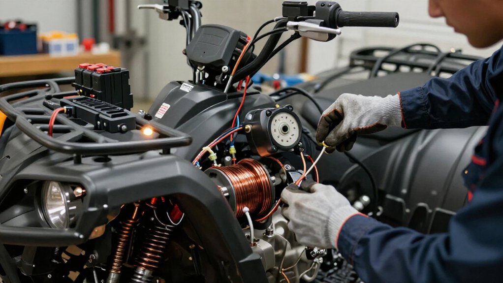
Your ATV’s stator generates AC, while the regulator/rectifier converts it to DC for the battery and lights.
Before upgrading, total the wattage of all lamps and accessories, then compare the load with your ATV’s specifications.
Measure battery voltage while the engine runs; expect about 13.5–14.5 volts near 3,000 rpm.
Dimming at idle may indicate low output.
Match bulbs to housing and beam specs, use correctly rated fuses and relays, and check connections for heat or corrosion.
A few additional checks can help you choose safely.
Lighting Wattage Limits
Add up the wattage of your headlights, auxiliary lights, and other electrical accessories to determine whether the stator can support the total load while maintaining the battery. Check each lamp’s rated wattage, then include heated gear and every accessory on the same charging system. This combined figure sets the demand your stator and regulator must handle. Compare it with your ATV’s specifications before choosing replacement bulbs.
Your regulator/rectifier should maintain about 13.5–14.5V for a lead-acid or AGM battery. Measure voltage at the battery with the engine running and accessories switched on. Above roughly 15.0V, you risk overcharging components; if voltage won’t stay in range, reduce the load and inspect the charging system before installing higher-wattage lamps. Verify the combined load, not bulb count.
Stator Output and Light Load
After confirming the total lighting load is within your ATV’s limits, check whether the stator can supply it at different engine speeds.
Your stator generates AC power while the engine runs. With few lights or accessories operating, the regulator may clamp system voltage to prevent overvoltage, so battery voltage alone won’t reveal stator output.
For a typical three-phase stator, set your meter to AC volts and measure between each pair of stator pins: 1,2, 2,3, and 1,3. Expect roughly 15–20 volts AC at idle and 50–70 volts AC when you raise engine speed. Compare all three readings under the same conditions; similar values indicate more consistent output.
If readings vary sharply, inspect connectors and wiring for resistance or damage, and consider weak windings. Regular measurements help separate stator output from regulated system voltage.
Lights Dimming at Idle
If your ATV’s lights dim or flicker at idle, the charging system may not be supplying enough voltage at low RPM, even if the lights brighten when you rev the engine. Measure battery DC voltage at idle and near 3,000 RPM: expect about 13.0–13.5V, rising to 13.5–14.5V. If it stays near 12.5V or falls, charging output is insufficient.
| Check | Expected result |
|---|---|
| Battery idle | 13.0–13.5V |
| Battery at 3,000 RPM | 13.5–14.5V |
| Stator pairs at idle | ~15–20V AC, even |
| Regulator warning | >15.0V or ≤12.8V |
Compare AC readings across pairs 1–2, 2–3, and 1–3; uneven or low output points to stator windings. Poor connections or grounds add resistance and sag voltage under load. Above 15.0V indicates overcharging; failure to rise above 12.8V signals undercharging. Either can destabilize lighting.
Lighting Circuit Components
You get AC lighting power from the engine-driven stator, whose output rises with RPM. The regulator converts that AC to controlled DC, keeping voltage within your battery’s charging limits.
You’ll also need sound wiring, grounds, and connectors to handle circuit loads without flicker or damage.
Stator Lighting Output
While the engine runs, the stator supplies AC power to the ATV’s lighting circuit, and output typically rises with RPM.
On a three-phase stator, you can check AC voltage between pin pairs 1, 2, 2, 3, and 1, 3. Common reference readings are about 15–20V AC at idle and 50–70V AC when revved. If your headlights and dash lights dim or flicker at low RPM but improve as RPM rises, weak or uneven stator output under load may be the cause. A healthy battery won’t restore power that the lighting feed isn’t generating.
Test winding resistance: readings across pairs should be similar, with no open-circuit indication (“OL”). Check each stator pin for continuity to the stator body or engine case; there shouldn’t be a short.
Regulator Voltage Control
Stator output varies with engine speed, so the regulator/rectifier limits voltage and converts the three-phase AC supply into a stable DC charging output for the battery and lighting circuit. That control protects bulbs and electronics from voltage spikes. With engine running near 3,000 RPM, check battery terminals: expect 13.5–14.5V. Above 15.0V signals a regulator that isn’t clamping.
Engine off, a lead-acid or AGM battery should rest at 12.6–12.8V before charging.
| Condition | Reading | Meaning |
|---|---|---|
| Engine running | 13.5–14.5V | Normal control |
| Engine off | 12.6–12.8V | Resting battery |
If lights dim or flicker at idle, test regulation when stator speed changes. For LiFePO4, choose a unit capped at 14.6V; shunt-regulator spikes can stress cells. Use your meter first.
Circuit Load Limits
Every part of an ATV’s lighting circuit has a current limit. Your stator and regulator/rectifier must supply the normal load plus added lights without letting battery voltage sag. Wiring, fuse, switch, and ground also have ratings; overloaded wiring can overheat, and undersized fuses or connectors can fail even while regulation appears normal.
A fuse protects wiring, not the lamp. If you exceed its rating, it may open; a connector may melt. The regulator doesn’t control excess current by itself.
High lamp demand leaves less charging headroom at idle, when stator output falls, so lights may dim or flicker. Match wattage to your ATV’s stated charging capacity. Then check voltage with lights on; keep lead-acid or AGM systems around 13.5–14.5V to avoid stressing the regulator.
Bulb Type and Beam Pattern
You’ll find halogen and other bulb types, such as H4, H7, or H11, vary by model and produce different output. Choose a beam pattern suited to your riding: reflector and projector designs shape the spread, cutoff, and foreground illumination.
Match the bulb’s base and wattage to your reflector spec to avoid glare and wasted light.
Bulb Type Options
Choosing an ATV headlight bulb means matching its base, beam pattern, and power draw to the housing and charging system. Older ATVs use halogen sealed-beam bulbs. They produce a wide, forgiving beam, but the reflector must focus it for visibility.
LED retrofits generate less filament heat and can deliver a sharper cutoff and steadier output. Yet an LED emitter may scatter in a reflector designed for a filament, so confirm the housing supports that bulb type.
HID/Xenon lamps offer lumen output and long throw, but require compatible ballasts and headlamps rated for HID optics to limit glare.
Use the exact base, such as H4/9003-style dual-filament or a single-beam bulb. Check wattage: a marginal stator or regulator can cause dimming at idle or flicker.
Beam Pattern Selection
Once the bulb fits the housing, select a beam pattern that suits your riding: low beam needs a sharp cutoff to limit glare, while high beam throws light farther for open terrain.
| Use | Pattern | Practical check |
|---|---|---|
| Low beam | Sharp cutoff | Control glare |
| High beam | Long reach | Open terrain |
Projector optics usually create a cleaner, more controlled cutoff than basic reflectors, helping you reduce oncoming glare. Halogen H4/H11-style bulbs offer simplicity but use power less efficiently; LED or HID can increase brightness only when your housing supports the output and you aim it correctly. Check wattage and current draw before changing patterns.
Poorly suited optics can create hot spots, cloudy edges, or uneven illumination. After installation, aim the headlight to manufacturer specifications. Test both low and high beams; even a small mounting or adjustment shift can send glare upward or weaken the usable low-beam cutoff. Choose for terrain, then verify the pattern at riding height.
Matching Bulbs to Reflectors
For a reliable beam pattern, match the bulb to the reflector’s design and focal point. Choose the specified family—such as halogen H4, H7, or H11, or compatible LED—and confirm its emitter or filament sits at the intended focal position. Use your housing’s voltage and wattage; halogen formats use 55 W or 60/55 W.
Too little output can leave you dim; excess heat can distort the reflector. If your reflector was designed for a halogen filament, a plug-in LED may shift the cutoff or hotspot because its chips can’t duplicate filament size and placement.
Check the housing label and test the beam: you want a sharp low-beam cutoff, not broad glare that blinds others. Verify mounting and aim; a compatible bulb can still misalign.
Auxiliary Light Wiring Methods
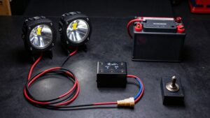
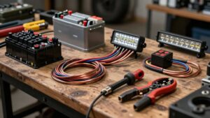
To add auxiliary lights without overloading the factory wiring, use a fused relay: power it from the battery or charging bus, trigger its coil from the headlight circuit, and run adequately sized leads directly to the lamps. Choose high-beam control if you want lamps to follow the main headlights; the OEM circuit then carries only coil current. Size relay output wires for load and run length to limit voltage drop. Give each lamp a clean ground, preferably dedicated.
| Check | Practical method | Reason |
|---|---|---|
| Load | 55 W ≈ 4.6 A each | Estimate draw |
| Feed | Fused battery bus | Protect branch |
| Test | Check voltage at idle | Confirm capacity |
Use waterproof connectors and dielectric grease; avoid daisy-chaining accessories. Check voltage at idle under full load; reduce lamps if it sags.
Overheated Connector Risks
When corrosion or moisture raises resistance at a connector, current generates heat right at the contact points.
Regulator and stator connectors can run hot under real load, so a weak connection may discolor plastic, melt the housing, or loosen pins even when charging voltage initially looks normal. Don’t treat a normal voltage reading as proof that the connector’s safe.
Inspect unplugged connectors for darkened terminals, softened plastic, or loose pins. A burnt or melted housing signals operation beyond safe current or temperature limits.
Clean the contacts, re-terminate damaged wiring, then retest the circuit under load. After inspection and reconnection, apply dielectric grease to help seal out water and reduce arcing. Check after use; renewed heat or discoloration means the connection still needs correction.
Overlooking Ground Corrosion
A clean-looking connector can still overheat if corrosion has raised resistance in the ground path. At idle, when stator output is lowest, voltage loss can dim or flicker your lights. Corrosion in an oxidized strap, frame contact, or harness pin may hide downstream of a battery charging test that appears normal.
- Inspect regulator/rectifier mounting points, battery-negative straps, and harness grounds; moisture and vibration often attack these joints.
- Look for brittle braid, green pin surfaces, or darkened connector shell; resistance can heat marginal contacts and soften plastic.
- Measure voltage at the lamp under load, not only at the battery, to expose ground-side drop.
You’ll clean ground to bare metal, tighten it against paint-free mounting surface, and apply dielectric grease at connector to slow moisture return.
Verify Fuse Ratings
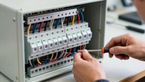
Check the lighting fuses against your ATV’s or UTV’s manufacturer specifications; the stamped amperage must match, since an oversized fuse can let an overcurrent damage the wiring.
Locate lighting-related fuses in the fuse box; compare each rating with your manual, which may list 10A, 15A, or 20A. Replace a discolored, cracked, or overheated fuse only with the same amperage and type. With the key off, inspect holder contacts for corrosion or heat marks; clean and tighten them, because poor contact can cause voltage drop and dim lights.
Remove the fuse and test continuity with a multimeter; don’t trust visual inspection. If fuses keep blowing after you verify wiring and stator/regulator output, troubleshoot abnormal current draw in that circuit, including a short in the headlight harness or an accessory.
Conclusion
Before adding lights, calculate your ATV’s available stator output and compare it with the load. Expect dimming at idle if output falls below demand. Inspect the regulator, connectors, and grounds; corrosion or heat damage can restrict current.
Choose bulbs and beam patterns for your needs, then wire auxiliary lamps through rated relays and fuses. Verify circuit limits before riding, and stop if wiring overheats or lights flicker. This protects components and keeps illumination reliable.