How to Install a Light Bar Without a Wiring Harness: DIY Relay Setup
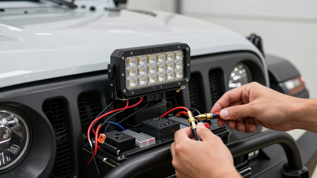
You can install a light bar without a harness by building a fused relay circuit.
Disconnect the battery negative terminal and use insulated tools.
Run battery positive through an inline fuse near the battery to terminal 30; connect terminal 87 to the bar’s positive lead, and ground its negative lead.
Connect terminals 85 and 86 to a low-current coil-control circuit, confirming trigger polarity.
Size wire, fuse, relay, and connectors for load and inrush; test aim.
Further checks help keep your installation reliable.
Relay Pinout and Fusing
Before wiring a light bar, identify the relay terminals: 30 and 87 switch the high-current power path, while 85 and 86 energize the coil.
You route battery positive through an inline fuse to terminal 30, then connect terminal 87 to the light bar’s positive lead. Terminals 30 and 87 remain open until the coil energizes. Ground the light bar’s negative lead to a solid chassis point or battery negative.
Commonly, connect terminal 85 to ground and terminal 86 to your switch’s trigger line; confirm the relay’s pinout and trigger polarity before wiring.
Choose a relay rated for the continuous LED load and compatible with the driver’s inrush current. Size the fuse for the light bar’s rated current and startup behavior, while ensuring it protects the smallest wire and connector. Coordinate fuse, relay, wire, and connector ratings to prevent overheating. A watts-to-volts estimate alone isn’t enough to select protection.
Gather Tools and Materials
With the relay pinout and protection requirements established, gather components matched to the light bar’s actual current draw and wiring run.
- Choose an automotive 4-pin relay rated for continuous load and LED-driver inrush, plus an inline fuse holder. Set fuse value and wire gauge from the light bar’s data sheet, using measured current as your baseline, not a wattage/voltage estimate.
- Use approved automotive primary wire rated to 60 volts or less, such as SAE J1128, and cut enough for the full route.
- Add closed-barrel crimp terminals, heat-shrink, a fused trigger switch, chassis-ground wire and ring terminal.
Gather crimper, stripper, zip ties, loom, and waterproof connectors for every exposed connection; the switch should energize only the relay coil, never carry the light bar’s full load.
Step 1: Disconnect the Vehicle Battery
To prevent accidental shorts while installing the relay, fuse, and switch, disconnect the battery’s negative (-) terminal and secure the cable clear of metal.
If your vehicle uses a security code, memory settings, or advanced infotainment modules, check its service information first; restoring power may require reinitialization. After disconnecting, wait a few minutes for the vehicle’s capacitors and ECUs to discharge before you touch fuse-box or relay circuits. Use insulated tools throughout this procedure.
Confirm no dashboard lights remain active, then use a multimeter or 12V test light to verify the relevant circuits are dead.
Keep the negative terminal disconnected until you finish, secure, and inspect all wiring. This prevents the fuse-fed battery side from energizing prematurely. Reconnect the terminal only after that check.
Step 2: Choose a Switch Location
Choose a cool, dry dash or console location you can reach comfortably from the driver’s seat, and keep the switch wiring run to the relay short. Mount it on a panel that stays cool and dry; the switch carries only low relay-trigger current, not the light bar load.
For independent operation from high beams or backup lights, position it to feed relay terminal 86 from a clean, fused +12-volt control source. If you want high-beam-linked operation, place the switch in series with the high-beam lead before it reaches the relay control circuit at terminals 85/86; that way, both conditions must be met.
Route the trigger wire away from sharp edges, moving parts, and heat sources. Protect it with abrasion sleeve where needed, and secure it with zip ties to limit vibration damage. Verify the path won’t interfere with pedals, steering, or airbag deployment zones before drilling or fastening the switch.
Step 3: Connect Relay to Battery
Before applying power, confirm your relay’s pinout: terminals 85 and 86 serve the coil, while 30 and 87 are the switching contacts. Connect terminal 30 to battery positive through an inline fuse. Place the fuse as close to the battery as practical, so the unfused wire run stays short.
Choose automotive wire and size the fuse for the light bar’s rated continuous current, accounting for any specified inrush or startup current. Confirm 87 is the switched output, but leave its load connection for the next wiring step. Check the relay datasheet if its pinout isn’t standard; some relays differ.
Before reconnecting or energizing the circuit, verify polarity and terminal connections: battery-side power must reach 30, and the load feed must leave 87. Secure the fuse holder and insulate exposed conductors to prevent shorts.
Step 4: Connect Bar’s Positive Lead
With the fused battery feed connected to terminal 30, run vehicle-grade wire from relay terminal 87 to the light bar’s positive (+) terminal. Size the wire for the bar’s rated current draw, including startup or inrush current, to limit voltage drop and prevent overheating. Protect the run from sharp edges, heat, and moving parts, and secure it against chafing.
Use suitable terminals to make an insulated connection at terminal 87 and the bar’s positive post. Confirm terminal markings: 87 is the switched output, and terminal 30 receives the fused battery feed. Before energizing, verify that the output wire reaches the marked positive (+) terminal. Reversed polarity can prevent operation and may affect LED drivers. Inspect the connection, then test the bar through the relay control.
Step 5: Ground the Light Bar
Connect the light bar’s negative lead to an OEM-approved chassis ground on clean, unpainted metal; a painted or rusty surface can create a high-resistance connection. Use a solid, correctly sized ground wire, and secure a ring terminal beneath a tight fastener.
The connection must resist vibration and moisture; don’t rely on a loose bolt or incidental contact. Keep the ground path dedicated rather than sharing it with unrelated accessories, whose return current can cause intermittent flicker.
If the chassis point isn’t suitable and you run the ground to the battery, size the wire for the bar’s current draw and the circuit’s total length to limit voltage drop and overheating. Once wiring’s complete, switch on the bar and measure voltage directly across its input with a multimeter. Near-battery voltage helps confirm the ground’s sound. Disconnect power before servicing the connection.
Step 6: Route Wires Through Grommets
Whenever a light-bar wire passes through sheet metal, route it through a rubber grommet to prevent the sharp edge from wearing through its insulation and causing a short. Choose a grommet, and drill a hole sized closely to its outside diameter so it fits snugly and limits water entry.
Cover engine-bay wire with heat-resistant loom before feeding the sleeved cable through the grommet; maintain abrasion protection across the opening. Tug the wire to confirm it stays put and the insulation hasn’t been cut or pinched.
Secure the cable with a zip tie inches from the pass-through to limit vibration. Keep the route clear of the steering column and pedals, and leave slack so steering lock or suspension travel won’t pull the wire tight.
Verify Beam Aim and Coverage
After securing the wiring, check the light bar’s aim on a level surface. Park facing a wall about 10–25 ft (3–8 m) away, then mark its center with tape. Turn on your headlamps first, then add the bar.
Confirm its brightest area stays centered and below headlamp cutoff height. The bar should enhance illumination without washing out or excessively flaring the wall. To evaluate coverage, move the vehicle forward a few inches at a time; ensure the hotspot remains aligned with your mark rather than drifting off-axis.
Aim the beam slightly downward to improve roadway visibility while reducing glare to other drivers. Recheck the pattern after adjustment, confirming the mounted bar and bracket haven’t shifted. If possible, drive at night and verify alignment over bumps.
Relay Chatters Under Load
If the relay chatters when the light bar turns on, its coil-control voltage may be dropping below the level needed to hold the contacts closed. Check terminal 85’s coil return and terminal 86’s switched signal under load; a weak ground or high-resistance switch can let voltage dip repeatedly. Painted or rusty mounting surfaces can worsen the ground drop.
| Symptom | Likely cause | Check |
|---|---|---|
| Chatter | Coil sag | Test 85/86 under load |
| Buzzing | LED inrush; undersized relay | Check contact rating |
| Hot feed | Wire/fuse sizing | Verify ratings |
Choose a relay rated above the bar’s continuous current and for LED inrush. Confirm the battery feed uses correctly sized wire and fuse; avoid long, unfused runs.
Disconnect power before repairs, and replace damaged or overheated parts. Don’t operate the light bar until you’ve corrected the fault.
Inspect for Corrosion Regularly
Inspect the light bar connectors and relay-side splices every few weeks, or monthly in wet or salty conditions, especially where road spray reaches them. Check for white or green powder, or dark pitting, around pins and crimp barrels; trapped moisture quickly reduces conductivity. Confirm connectors are seated; inspect seals or grommets for cracks or looseness that allow water ingress.
DIY terminations need close checks: look for lifting, gaps, or moisture staining at exposed crimps and heat-shrink seams. If corrosion appears, disconnect power. Clean contacts with suitable electrical cleaner and dry them thoroughly. Apply inhibitor only to terminals or external surfaces, never behind the harness inside a sealed joint. Repair compromised seals promptly, then verify secure connections before safely restoring power to the light bar.
Conclusion
Before you use the light bar, confirm the relay pinout and fuse rating, secure every connection, and verify beam aim and coverage. Keep the wiring clear of heat and moving parts, route it through protected grommets, and inspect for corrosion regularly.
If the relay chatters under load, switch off the lights and diagnose the fault before driving. You’ll protect your vehicle and reduce electrical risk by disconnecting the battery during installation and testing safely afterward.