How to Wire Amber Strobe Lights With a Switch and Sync Pattern
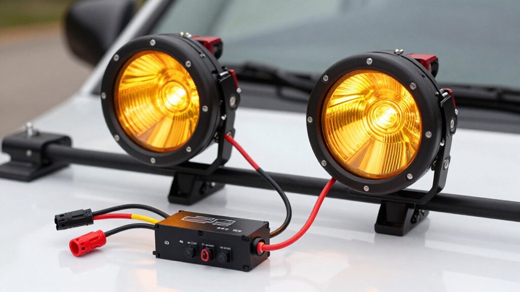
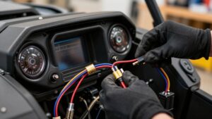
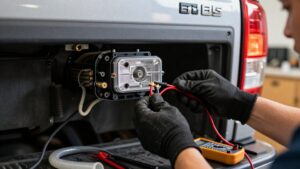
With ignition off, disconnect the battery’s negative terminal before wiring strobes. Check each model’s diagram, then connect red to fused 12-volt power through a switch, black to ground, and the designated sync lead as specified; colors vary. Set compatible lights to the same flash pattern and join sync wires.
Insulate and secure connections, route wires through grommets, and restore power when dry.
If timing differs, verify supply, ground, and sync connections; the steps below explain these checks.
Amber Strobe Wiring Outcome
Wire each amber strobe as its model specifies: connect red to 12V+, black to ground, and use the designated trigger or sync wire, yellow, brown, or white, to control pattern changes. When you link modules, tie their corresponding sync/trigger wires together so both units respond to the same pattern command. Match their patterns first using each model’s pattern-select lead; then follow its stated power-cycle or sync-touch procedure.
On STR63AWF/STR63AF units, hold the yellow lead at 12V for about five seconds to enter sync, then briefly touch it to 12V whenever you want both lights to advance together. Secure every connection, insulate exposed conductors, and confirm polarity before energizing the circuit. For asynchronous wig-wag operation on these models, power only one green wig-wag lead while keeping red, black, and yellow connections as specified. This lets pattern changes remain coordinated while the flashes alternate. Disconnect power before altering wiring. Use suitable fusing for the supply circuit.
Verify X-Pattern Compatibility
Before connecting the lights, confirm both units support X-pattern synchronization and check their model-specific wiring diagrams for the sync or trigger lead.
Match the model and part number; two similar-looking modules may use different control logic. Identify each harness lead by its own diagram, since sync colors can vary among yellow, brown, or green. Never assume color alone defines function.
Confirm the manufacturer’s diagonal pairing before joining sync leads:
- Group A: front-left with rear-right.
- Group B: front-right with rear-left.
- Keep Group A and Group B sync wires separate.
Use a current-limited test supply and the control procedure to command matching patterns. Both groups should alternate diagonally; if they flash independently or fail to alternate, stop and recheck compatibility, lead identification, and grouping before installation.
Step 1: Disconnect Vehicle Battery
With the ignition fully off, disconnect the negative (–) battery terminal first to reduce the risk of a short while handling the strobe wiring.
Confirm the terminal markings before loosening the clamp; negative is typically black and positive is typically red. Use the vehicle manual if labels aren’t clear. Keep tools clear of the terminals and metal.
For isolation, disconnect the positive (+) terminal only after removing the negative clamp. Position each loose terminal so it can’t touch metal or the other terminal. Wait a few minutes before handling the strobe wiring; this allows capacitors in vehicle electronics to discharge.
Don’t reconnect the battery until all strobe power and ground leads, switch feed, and sync trigger wires are secured and routed away from pinching or abrasion. Ensure connections remain isolated before reconnecting.
Step 2: Identify Strobe Wire Colors
Identify each lead from the light’s model-specific wiring diagram; colors aren’t consistent across amber strobe models. With the vehicle battery still disconnected, verify every conductor before you connect power or ground.
Most STR63, STR-MX, and STR1-series modules use red for 12V-positive and black for ground, but some models specify white as ground. Treat yellow, brown, or white as a possible trigger only when the diagram confirms it; trigger reference may be 12V-positive or ground. On STR63AWF/STR63AF lights, yellow is the trigger, while green serves asynchronous wig-wag only.
STR-MXA/MXR/MXW models use brown as the trigger and white as ground. STR1A/1R/1W/1B, STR61, and STR41 models use white as the trigger; green’s role varies by sub-series. Label leads before routing. Keep unused leads insulated and follow the specified terminal connections.
Step 3: Select Matching Flash Patterns
Set the same flash pattern on every amber light before connecting their sync wires. With each unit powered from 12V+ and ground, use its pattern-select trigger wire to advance modes. Follow the manufacturer’s timing steps, using brief pulses at the specified trigger voltage; don’t guess pulse duration.
After each pulse, inspect the output and record the pattern number so you can compare units. If a model supports reverse selection through a longer hold, use that function to bring each light to the same pattern number. Then activate each trigger and verify that every unit responds; if only one changes, repeat the selection procedure on the others. Don’t assume matching appearance means matching pattern numbers. Complete and verify pattern selection before proceeding to the wiring step.
Step 4: Connect Switch and Sync Wires
Before applying power, connect each strobe’s red wire to 12V+ through the switch and its black wire to ground; join the compatible sync/trigger wires as the manufacturer specifies. Mount the lights securely, and verify polarity and connections before energizing the circuit.
Place the switch in series with each strobe’s red power lead so it controls 12V+; don’t put it in the ground or sync wire. For synchronized operation, connect only compatible trigger leads, such as yellow, brown, or white, depending on the model, together.
Follow the module’s instructions to enter programming mode: touch the designated sync/trigger wire to 12V+ or ground, as specified, for the required hold time. Keep trigger contact isolated from unrelated leads, and use the specified voltage only for that model.
Step 5: Test Switch Before Reassembly
Once you’ve checked the wiring, power the strobe from a known-good 12V source, red to positive and black to ground, and toggle the switch to confirm the light turns on and off. Keep the strobe free of hardware during this bench test, and disconnect power before changing connections. With power on, verify the light responds to the switch.
If you’re using synchronization, confirm the yellow trigger and sync leads follow the manufacturer’s diagram; for STR63AWF/STR63AF, tie both yellow wires and power and ground the lights. Briefly touch the yellow wire to 12V+ to cycle patterns, then check that switching doesn’t disrupt synchronization. For sync setup, hold yellow to 12V+ for about five seconds until the lights flash; release it and verify they turn off for a few seconds.
Step 6: Route Wires Through Grommets
To protect the insulation from sharp sheet-metal edges, drill a correctly sized opening and fit it with a rubber grommet before routing the strobe wires. Push the grommet firmly into the body panel opening. Feed the strobe’s power leads and trigger/sync wires through it; route them in separate bundles when possible to keep the installation organized.
Leave a service loop of a few centimeters inside the vehicle so you can remove or reposition the light without stressing conductors. Secure the wiring immediately beyond the grommet with a clamp or loom tie to prevent vibration from pulling on the seal. If the route passes near moving parts or heat sources, cover the wires between the grommet and mounting area with split-loom or conduit for abrasion resistance.
Verify Switch Indicator Illumination
With the strobe connected, red to switched 12V+ and black to a solid ground, turn it on and confirm the switch indicator illuminates with the lights. Toggle the switch off and on. The indicator should go dark with the strobes and illuminate whenever they receive power; neither should operate without the other.
Use a meter to verify switched 12V+ reaches the strobe’s red lead. With power off, check connections; confirm the switch suits 12V DC and the black ground is secure if the indicator stays dark. For multiple lights, compare it with the main power switch; sync wires coordinate flashing only after power is present. Don’t confuse indicator wiring with sync wiring, and keep the circuit de-energized before correcting any connection to prevent an accidental short, shock, or equipment damage.
Fix Inconsistent Sync Timing
If the strobes flash out of step, confirm they’re the same model and set to the same pattern before checking the wiring. Use this sequence to isolate the fault safely.
| Check | Action | Why |
|---|---|---|
| Supply | Share one solid 12V source and common ground | Prevents drift |
| Sync | Tie yellow wires together; keep connections tight and insulated | Loose crimps disrupt timing |
| Trigger | Join brown wires on one common bus | Avoid separate triggering |
For STR63AF/STR63AWF touch-to-sync, hold yellow to 12V for about five seconds. Release when both lights turn off briefly; then tap yellow to advance patterns together.
Disconnect power before correcting wiring, and verify insulated connections before restoring power. If timing still differs, recheck selected patterns, polarity, and every crimp; don’t trigger lamps independently or mix supply grounds across lights.
Clean Amber Lenses Monthly
Clean amber strobe lenses at least monthly with a soft microfiber cloth and mild soap-and-water solution or a lens-safe cleaner to remove dust and road film that can dim the output.
Before you begin, switch the lights off and confirm the electrical connections are dry, especially around wire-entry seals. Wipe gently; don’t use abrasive pads, which can haze the plastic and reduce transmission. Rinse the lens thoroughly with clean water, then dry it completely with a microfiber towel so streaks don’t obstruct the amber output.
As you clean, inspect for scratches or cracks. Damage can scatter light and lower perceived strobe intensity. Replace a damaged lens or light assembly according to the manufacturer’s instructions, and restore power only after the connections and surrounding area are dry.
Conclusion
Finish only after you verify X-pattern compatibility and select matching flash patterns. Disconnect the battery before inspection or repairs; confirm wire functions rather than relying on color alone. Route conductors through protected grommets, secure connections, and test switch indicator illumination.
If synchronized strobes drift or flash inconsistently, recheck polarity, grounds, and pattern settings. Keep lenses clean monthly. Restore power only when wiring is insulated and clear of hazards. Have a qualified technician correct unresolved faults.