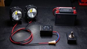
12V Wire Gauge Amp Chart for Off-Road Lights and Accessories
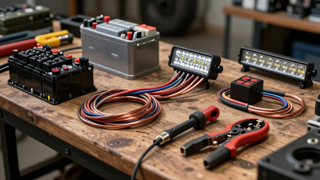
For 12V off-road lighting, size wire for load current and round-trip distance.
A 72W bar draws about 6A; a 180W bar draws about 15A.
Use 16 AWG below 10 ft for 55–65W, and 14 AWG at 10–20 ft.
180–300W needs 12 AWG below 10 ft or 10 AWG at 10–20 ft.
Fuse above current but below wire ampacity.
Keep voltage drop near 3%, under 5%.
Use a relay above 10A.
More guidance covers connections and checks.
LED Bar Current Draw
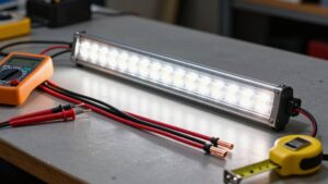
A 12V LED bar draws approximately its wattage divided by 12: a 72W bar uses about 6A, while a 180W bar uses about 15A. Use that estimate to predict the load your lighting circuit must carry; actual current can vary with operating voltage and product design.
High-power bars commonly range from 180W to 300W, drawing roughly 15A to 25A at 12V. That demand makes connections and correctly rated components essential. Protect the positive feed with a fuse sized for the circuit, following the manufacturer’s specifications. A relay lets the switch control the load without carrying the bar’s full current.
Don’t assume stated wattage gives you the exact draw under every condition; check the label or manufacturer’s data when available. If you’re powering multiple lamps, add their expected currents before selecting protective components. Secure wiring away from heat, abrasion, and moving parts to reduce failure risks.
Amp-and-Distance Wire Chart
Once you’ve estimated the load, choose wire by current and round-trip distance: the run from the battery to the light and back through the ground path. Calculate current first: divide watts by 12V; 180W is about 15A, while 40W is about 3.3A. Match that result to the chart.
| Load | Round-trip distance: typical wire |
|---|---|
| 12–24W (~1–2A) | Under 10 ft: 18 AWG; 10–20 ft: 16 AWG |
| 55–65W (~4.5–5.5A) | Under 10 ft: 16 AWG; 10–20 ft: 14 AWG |
| 180–300W (~15–25A) | Under 10 ft: 12 AWG; 10–20 ft: 10 AWG |
| Voltage drop | Aim near 3% for critical circuits; keep near or below 5% |
Longer runs or heavier loads may require a larger selection.
Check your actual route, connections, and load before energizing.
AWG and Copper Ratings
In AWG, a lower number means thicker copper: 10 AWG carries more current and loses less voltage than 14 AWG over the same run. Typical 12V off-road light circuits use copper wire from 10 to 16 AWG. Choose 10 or 12 AWG for higher-current accessories; 14 or 16 AWG often suits smaller loads.
As a general guide, 8 AWG may carry up to about 60A, 10 AWG up to 30A, 12 AWG up to 20A, and 14 AWG up to 10A. Treat these figures as guidance, not guarantees: your wire’s insulation and temperature rating also affect safe capacity.
Longer runs increase resistance and voltage drop, even below ampacity. Check circuit length and wire ratings; choose copper that limits heating and maintains voltage under load.
Fuse Sizing by Circuit Load
Calculate circuit load as watts ÷ 12V, then choose the next standard fuse size above steady current—but never above the wire’s safe ampacity. Account for LED startup surges and protect long wire runs; a suitable fuse can prevent overheating even when the accessory operates normally.
Mount the fuse as close to the battery as possible, and use a relay for loads over roughly 10A.
Match Fuse to Load
Choose a fuse that protects the wire: rate it slightly above the light’s steady-state draw but below the wire’s safe ampacity. For example, a light bar drawing about 15 A on 12 AWG wiring commonly uses a 20 A fuse. Confirm the lamp’s stated running current; voltage and driver efficiency affect draw.
If you group lights, add their steady-state currents before choosing the circuit rating. LED drivers may briefly draw nearly three times their running current at startup, so an undersized fuse can trip repeatedly even when the operating load is acceptable. For groups above roughly 10 A, use a relay to reduce current through the switch and limit switch heating and voltage drop. Mount the fuse within the first few inches of the battery lead.
Protect the Wire
Protect the wire, not just the LED, by placing a fuse close to the battery—ideally within the first few inches of the power lead—and sizing it above the circuit’s steady-state draw but below the wire’s safe ampacity.
For example, a 15 A load on 12 AWG wire often uses a 20 A fuse, if installation conditions permit. For loads around 10 A or more, use a relay and suitable fuse to protect the harness.
If fuses blow repeatedly or lights dim or flicker, inspect the circuit; don’t simply install a larger fuse. Warm wiring at connectors or bends also signals trouble. Recheck fuse rating and wire gauge for the full round-trip distance; long runs increase voltage drop and heat. Never exceed the wire’s safe capacity.
Account for Startup Current
Even with wire ampacity accounted for, a light’s startup current can influence fuse selection: some LED drivers briefly draw nearly three times their running current at power-on.
Size the fuse based on the light’s steady-state draw, but ensure its rating remains below your wire’s ampacity while tolerating anticipated inrush. A 15-amp light bar may commonly use a 20-amp fuse on appropriately rated wire; unusually high driver inrush may call for checking the fuse type and time-current curve.
For loads above about 10 amps, add a relay to reduce switch-contact stress and manage the surge path. Repeated blown fuses without a clear short may suggest that inrush at startup exceeds the fuse’s tolerance, not a typical-running overload. Check driver data and circuit condition; never exceed your wire’s safe ampacity.
Choose the Next Standard Size
Once you’ve calculated the light’s steady-state draw in amps (watts ÷ 12V), select the next standard fuse size above that load—but never exceed the wire’s safe ampacity.
A 180W bar draws about 15A (180 ÷ 12 ≈ 15), so with correctly sized 12 AWG wire, a 20A fuse typically suits the steady load.
If your calculated draw falls between available fuse ratings, move up one standard size only if that rating remains below the wire’s maximum safe ampacity. Otherwise, use heavier wire or reduce the circuit load; don’t install a larger fuse to stop nuisance trips.
For circuits above roughly 10A, use a relay rated for the load so the switch doesn’t carry the current. Allow for LED-driver inrush when verifying fuse selection.
Place Fuses Near Power
Place the fuse within the first few inches of the battery’s positive lead to minimize the length of unprotected wire. Size it from your circuit’s steady-state current: divide accessory watts by 12 volts, then choose a rating slightly above running draw but below the wire’s safe ampacity.
For example, a 15-amp light bar on correctly sized wiring commonly uses a 20-amp fuse to prevent nuisance trips. For loads above roughly 10 amps, use a relay; some LED drivers draw nearly three times running current at startup, affecting fuse and relay selection. If fuses keep blowing without an obvious short, inspect wire gauge and check for voltage drop or heat at connectors and bends. Undersized wiring can overheat and trigger protective shutdowns; fix it first.
Voltage-Drop Calculation Steps
To size a 12V circuit for acceptable voltage drop, calculate current by dividing watts by 12—for example, 180W draws about 15A and 36W about 3A—then measure the full round-trip conductor length from the battery to the light and back to ground. Use Vdrop = 2 × current × resistance per unit length × one-way length; the factor of two accounts for the return path.
Set a ceiling: target 3% (0.36V) for sensitive electronics; allow up to 5% (0.6V) maximum. Check the calculated drop against wire-resistance data for each AWG. If between sizes, choose thicker wire and recalculate.
Recheck runs over 15–20 ft one way or loads above 100W. Use the total round-trip length when entering the value in your gauge chart throughout the circuit.
Connector Temperature Limits
Monitor connectors and terminals for heat; correct wire gauge won’t prevent a loose or poorly crimped joint from developing high resistance and overheating.
With the correct AWG, crimps, junctions, or connector blocks can create localized hot spots. Keep connector and terminal temperatures below the cable’s insulation rating, 105°C minimum and often 105°C or 125°C.
If insulation feels noticeably warm during operation, or gets hot near bends and terminals, stop and inspect for excessive resistance, undersizing, or loose contact.
Treat relay and terminal connections feeding high-current LED bars as hot spots. Use the same or larger AWG than the load harness, and make tight, properly crimped connections. Fuse the circuit near the battery and stay within wire ampacity; higher current accelerates heat rise and increases terminal voltage drop.
Battery and Alternator Limits
Even correctly sized wiring can’t compensate for a charging system that can’t sustain the load: at 12V, a 180W light draws about 15A, while a 300W bar draws about 25A. Your alternator may deliver far less than its rated maximum at idle, so the bar can pull battery voltage down, causing dimming or flicker when output can’t cover the lights and other accessories.
Budget every load against realistic available output: if your lights draw 10A and accessories draw another 10A, the system must sustain about 20A. Confirm that your battery and alternator can support the bar’s steady current, often 10–25A, without prolonged under-voltage. Wire-gauge charts assume continuous operation at the intended current; verify capacity before installation.
Also account for possible LED-driver startup spikes, which can briefly increase demand. If voltage sags, your circuit may not deliver its planned performance, even with correctly selected wire. Check output under operating conditions, especially at idle with accessories running.
Connector Corrosion Prevention
Road spray and mud can drive moisture into 12V light connectors, causing corrosion and resistance that may lead to dimming or flicker. Protect each connection with a sealed, waterproof connector and adhesive-lined heat-shrink tubing; both block moisture wicking into terminals. Apply dielectric grease to mating surfaces, not inside conductor crimps, so it displaces moisture without contaminating the crimp.
- Size wire for the load; a 180 W lamp draws about 15 A, so don’t undersize.
- Place fuse, relay, and main power junctions near the battery to limit exposed, unprotected wiring.
- Inspect outdoor connections periodically; clean and re-grease sound mating surfaces.
- Green/white oxidation or melted insulation? Cut back, re-crimp, and reseal promptly.
Heat accelerates connector damage outdoors; proper sizing and prompt repairs protect your lights and reduce failure risk.
Relay Terminal Identification
To wire a standard 12V SPST relay, connect fused battery positive to terminal 30 and the light’s power lead to normally open terminal 87; terminals 85 and 86 operate the coil. Use your switch to energize the coil: feed switched 12V to one coil terminal and ground the other. Check relay markings because some coils require specific 85/86 polarity.
- Terminal 30 receives battery positive through a fuse sized to protect the supply wire under load.
- Terminal 87 powers the lights only when the relay energizes.
- Don’t use 87a; it’s normally closed and may leave the load powered unexpectedly.
- Follow marked coil polarity; otherwise, verify whether 85 and 86 can be swapped.
- If lights stay off, check 30-to-87 wiring and switched 12V across the coil.
Conclusion
Choose wire gauge from your accessory’s current draw and circuit length, then verify voltage drop and insulation temperature ratings. Fuse each circuit near its power source, sizing the fuse to protect the wire—not merely match the light’s load. Check that connectors, relays, battery, and alternator can handle the demand, and protect connections from corrosion.
Before powering your setup, confirm polarity, terminal identification, and secure routing. If you’re unsure, consult a qualified installer; undersized wiring can overheat and cause a fire.