
How to Install Pod Lights on a Truck Bumper: Mounting and Wiring
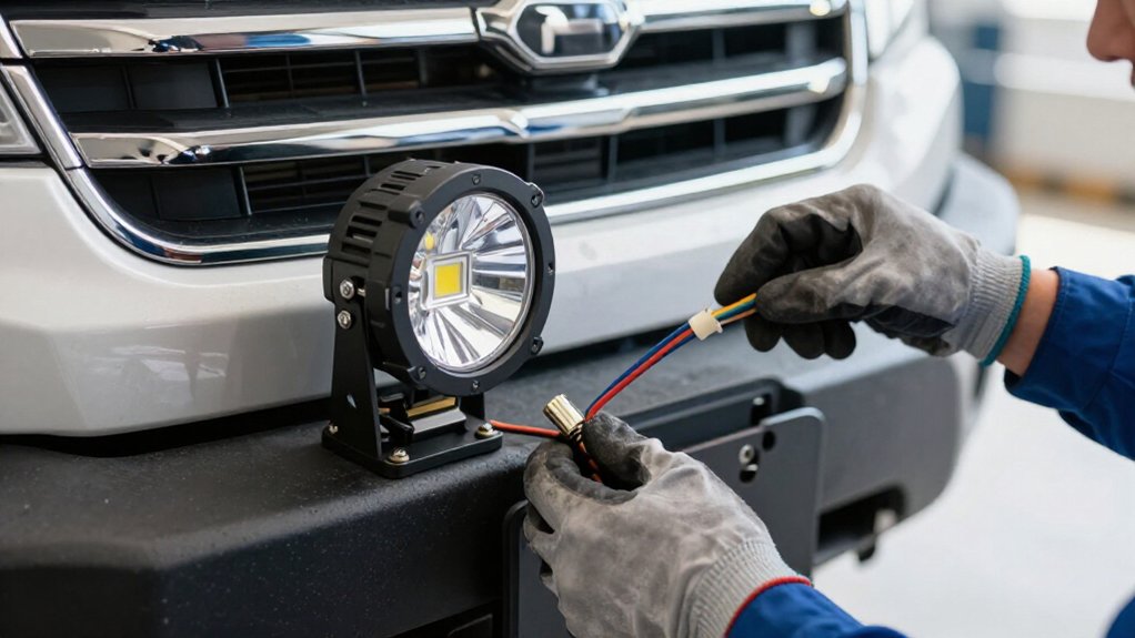
Disconnect your battery’s negative terminal before wiring.
Mark spots on a bumper, check behind it for hidden components, then center-punch and drill pilot holes.
Deburr and protect bare metal.
Fasten brackets, leaving pivots loose to aim pods slightly down and outward, lighting tire edges about 10–30 feet ahead.
Wire through a fused relay harness, ground to bare chassis metal, secure wiring in loom, verify beams, and torque hardware to spec.
Further checks can catch overlooked faults.
Expected Fit and Beam Aim
For trail use, aim the bumper-mounted pods slightly downward and outward so they light the ground about 10–30 feet ahead and reach the outer edges of your front tires, revealing ruts and rocks before you reach them. Loosen the bracket pivot bolts and mounting hardware just enough to adjust each beam, then compare the patterns on level ground. Confirm both pods illuminate evenly before you tighten the hardware to the manufacturer’s specified torque.
Take a short nighttime drive in a controlled area and check for dark gaps, glare toward the cab or nearby people, and a cutoff set too high to reveal ditch-line hazards. Flood beams should spread across lane edges and the ditch line; spot or combo beams extend visibility farther ahead. For work lighting, aim straighter forward and higher, but keep trail beams low so they don’t skip over obstacles.
Recheck aim after tightening. Keep nearby people clear of the beam during checks, and adjust only when safely parked.
Relay Harness and Fuse Checks
Before finalizing the wiring, check that the relay harness is rated for your pod count and that its inline fuse matches the harness and lights’ current draw.
- Keep the inline fuse accessible on the relay harness’s positive lead, not buried behind trim, so you can inspect or replace it safely.
- Attach ground to clean, bare chassis metal or the harness’s designated ground; a high-resistance connection can cause voltage drop and erratic output.
- Before final hookup, optionally use a multimeter at the fuse tap or positive lead to verify commanded battery voltage. Then switch on both pods before tightening everything; reseat and secure relay and fuse connections against vibration and moisture.
If either pod stays dark, switch off power and correct wiring before use.
Step 1: Mark Bumper Mounting Spots
Choose flat, rigid bumper locations with enough backing to support the pods without flexing over bumps. Position each bracket where the bumper can carry its load during vibration and impacts. Check behind the bumper for clearance around the bracket, wiring pass-through, and pod’s aiming pivot; make sure none will interfere with existing components.
Hold the bracket in place and mark its holes as a template. Measure from matching reference points, such as the bumper edges or frame centers, to verify left-right symmetry before drilling. If no suitable holes exist, mark drill targets for the specified hardware.
Use masking tape or a scribe to make each target visible and accurate. Drill a pilot hole first, then enlarge it with the correct metal bit. Deburr every hole, then protect exposed metal with touch-up paint or rust inhibitor.
Step 2: Disconnect the Negative Battery
With the bumper mounting spots marked, disconnect the battery’s negative (–) terminal before handling the pod-light wiring. This prevents accidental shorts, blown fuses, and damage to vehicle electronics. Wait a few seconds after removing the terminal so residual electrical charge can dissipate.
Keep the terminal disconnected while you route and secure the harness; even a mis-crimp or stray wire strand can trigger a high-current fault.
Before restoring power, verify the relay harness connections, inline fuse placement, and grounding point are correct. Don’t accept connections that are merely close enough. Seat each connector and apply dielectric grease where needed.
Leave the negative terminal disconnected until you’ve completed these checks and the wiring is secure. Then reconnect it only for your final power-on test and aim verification.
Step 3: Drill Bracket Pilot Holes
Position each bracket on the bumper, mark its pilot-hole locations, then use a center punch to keep the drill bit from wandering.
Select a bit sized for the bracket hardware, or start slightly undersize. Wear eye protection and check behind the bumper for hidden components. Hold the drill square to the metal; use steady pressure to create clean holes without forcing the bit. Test-fit the bracket before final drilling or fastening, and check that it sits flat and square.
Deburr both sides so sharp edges won’t damage wiring insulation or promote corrosion. Coat bare metal with touch-up paint or rust inhibitor. Keep installed hardware slightly loose so you can adjust pod aim up, down, in, or out after the wiring and lighting test.
Step 4: Crimp and Seal Wire Connections
Crimp the harness and pod pigtails with the correct insulated terminals, using a proper crimp tool rather than pliers. Tug-test each connection to verify the conductor holds securely. Slide adhesive-lined heat-shrink tubing over every crimp and heat it until adhesive flows around the wire, forming a moisture barrier.
This protection matters on bumper-mounted wiring exposed to spray and road debris.
Before seating each water-resistant connector, apply a thin coat of dielectric grease to the contact surfaces to help resist corrosion and moisture intrusion. Route connectors upward where possible to limit water pooling. Keep sealed joints clear of rubbing points and hot exhaust components.
After assembly, inspect the bumper brackets for pinched wires. Cover any remaining exposed conductors with heat shrink or equivalent sealed terminals.
Step 5: Set the Switch Location
Once the wiring connections are sealed, choose a cab switch location the driver can reach without obstructing airbags, vents, factory controls, or steering-wheel movement. Before drilling or attaching the switch, check behind the panel for wiring and confirm the position suits your reach while seated.
Plan the route to the engine bay through an existing firewall grommet; don’t pass the lead across bare sheet metal, where vibration can wear through insulation. With a relay harness, connect the switch only to its low-current control wire, never the high-current feed, to keep switch current within its rating.
Secure excess lead away from pedals, the steering shaft, and hot parts, leaving service slack. Before replacing trim, switch on and verify both pods illuminate, check connectors are fully seated.
Step 6: Torque Bracket Fasteners Properly
Snug the bumper bracket bolts first, then leave the pivot bolts slightly loose so you can aim each pod without fighting the hardware. Use a wrench or socket that matches the fastener size. Once both pods illuminate and you’ve aimed each beam, for example, low for trail-edge coverage, tighten the bracket fasteners firmly before driving.
On multi-point brackets, tighten evenly to prevent tilt or misalignment, and remove any play without over-tightening beyond the hardware maker’s specification. After tightening, inspect the harness: confirm it has slack and isn’t pinched beneath the bracket or between metal surfaces. After a dark test drive, inspect and tug each bracket bolt and connector. If vibration has shifted anything, correct the routing or alignment and retighten the fasteners before use.
Check for Radio Interference
With the brackets secure, power on the pod lights and monitor AM/FM and any nearby two-way radio for static, buzzing, or chirping.
Check the relay harness ground at clean chassis metal or battery negative through the harness. Confirm each connector is fully seated and protected with dielectric grease. Route pod-light wiring away from the factory antenna lead and radio power and ground wiring.
Secure crossings with split loom or conduit and zip ties to limit electromagnetic coupling.
If you hear interference, don’t ignore it: add clip-on ferrite cores to harness leads near the switch or relay. With the vehicle safely parked, perform a drive test with AM and FM radios on. Note whether engine speed or load changes affect reception before you finalize the installation.
Diagnose Flickering Pod Lights
If your pod lights flicker, start by checking the relay harness wiring: confirm the fused battery lead connects to positive and the grounds attach to clean chassis metal. With the truck off, inspect bumper connectors for secure seating, then check for chafed or heat-damaged insulation near sharp edges, exhaust parts, the fan, and steering shaft. Reroute damaged runs through loom and secure them clear of moving or hot components.
| Check | Finding | Action |
|---|---|---|
| Load | Switch undersized | Match rated amps |
| Isolation | Flicker remains | Test harness output |
Match switch and relay ratings to the pods’ current; overload can cause blinking. Test at the harness output or swap in a known-good relay or switch. Power staying steady points to a pod driver. Disconnect battery before repairs; never bypass the fuse.
Prevent Connector Corrosion
To prevent connector corrosion, apply dielectric grease to each bumper-area connector before fully seating it, then tug-test the connection to confirm its lock is engaged. Give extra attention to plugs exposed to road spray and condensation. Whenever possible, route each connector above its harness so water drains away instead of pooling inside the connector body.
Cover wiring with loom or split conduit, and secure it with zip ties; keep leads clear of sharp metal edges that could abrade insulation, damage seals, and admit moisture. Periodically inspect power and ground electrical points for corrosion. Road salt accelerates oxidation, and an IP67 or IP68 light rating won’t protect poorly sealed connections.
Disconnect power before cleaning or repairing a corroded joint, and restore the seal before reconnecting.
Conclusion
With the pods mounted, wired, and tested, confirm the beam aim meets your needs without blinding oncoming drivers. Recheck relay, fuse, and connector security, then inspect the lights for flicker or radio interference.
If either issue persists, switch off the system and diagnose the wiring before driving. Protect exposed connections against moisture and corrosion. After your first trip, check the fasteners again for looseness. Disconnect the negative battery cable before making any further wiring changes.