How to Install Whip Lights on a UTV: Mount, Wire and Flag-Test
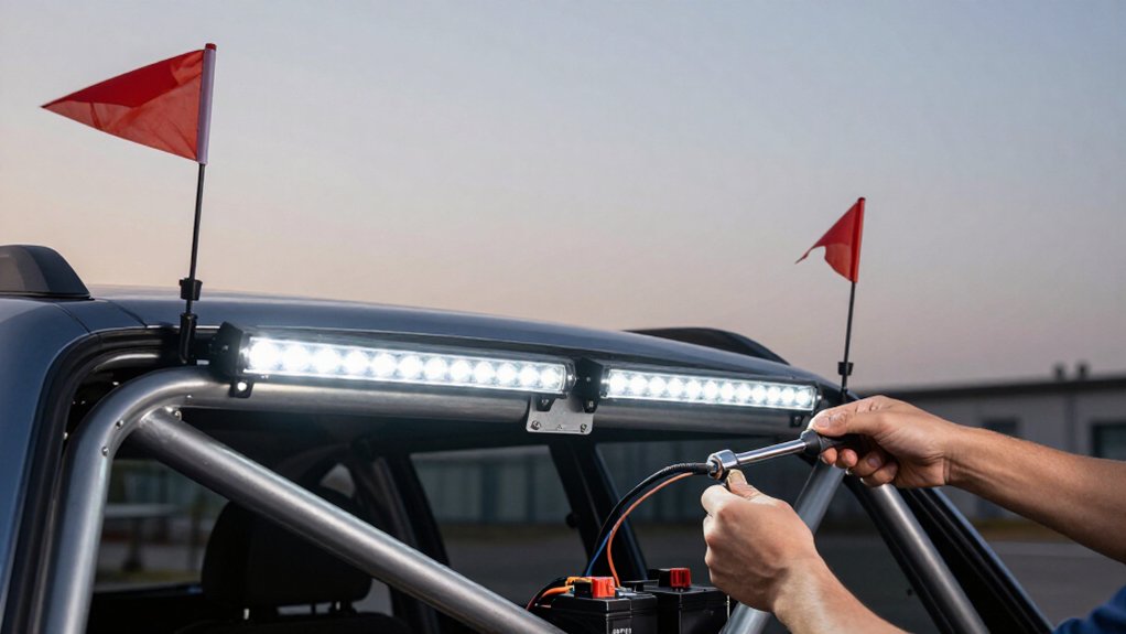
You can install UTV whip lights in about one to two hours. Mount each whip securely to a solid rear frame or roll-cage point, following the kit’s torque specifications.
With ignition off, disconnect the battery’s negative terminal before wiring. Match harness connectors, pinout, voltage, and fuse ratings to your kit.
Route protected wiring, secure it, and check full suspension clearance.
Reconnect, flag-test, then verify every mode and both whips. The steps below cover common faults.
Expected Installation Time
Most UTV whip light installations take about 1–2 hours, depending on how easily you can mount the bases and route the cables around the cage. Your timing depends on cage access and careful cable routing. Two symmetrical rear-corner whips usually install faster than nonstandard front or side placements.
Use zip ties every 6–8 inches for a neat run; protect openings with loom or grommets. Keep wiring clear of exhaust heat, suspension movement, and pinch points; careful routing can bring the job close to two hours. Power both whips, verify controls, patterns, and colors, then inspect for pinched or stretched wires.
Allow 15–30 minutes for this flag-test; it helps prevent rework. Make adjustments with the vehicle off, and secure all wiring before your first ride.
Harness and Connector Compatibility
After securing the wiring, verify that the harness matches your whips and controller in connector style and pinout; many RGB systems require a dedicated harness. Before connecting power, check these points:
- Match the harness voltage and current ratings to your UTV supply and the whips’ draw; most UTVs use 12 volts.
- Confirm fuse rating, placement, and any relay requirements against the manufacturer’s specifications; mismatched protection can cause failures.
- Use waterproof connectors that fully seat and lock; heat-shrink crimp joints to resist vibration and moisture.
- Route enough length to reach the controller without tension, then secure with ties and loom, clear of moving parts, heat, and abrasion.
Don’t splice individual leads when your RGB kit specifies a dedicated harness; verify every connection before applying power.
Step 1: Disconnect the UTV Battery
Before routing or crimping wires, turn off the ignition and disconnect the battery’s negative terminal first; remove the positive terminal if needed.
If your whip harness has fused or relay power leads, disconnect the battery anyway: contact at a live fuse or relay input can spark and cause a short. Confirm the UTV has powered down; no accessory lights or displays should remain active before you handle LED whip connections.
Keep the removed terminals clear of metal. Cover them with insulated caps, or position them so they can’t bridge the battery posts. Don’t let a tool or loose lead span the terminals, either. Once mounting and wiring are complete, reconnect the battery before you fully secure the wiring with zip ties.
Then perform a brief flag-test power check, watching for normal whip-light operation. If you see a spark or heat, disconnect power and inspect connections before continuing.
Step 2: Plan Your Wire Route
Plan a protected path from each whip location to the controller or splitter, following existing cage and frame routes where possible.
Keep the harness inside the machine’s structure, routing it along the inside of roll-cage tubes when practical. Secure it with zip ties every 6–8 inches so it can’t whip, sag, or contact moving parts. Keep clear of hot exhaust, suspension travel, driveshafts, and pinch points where cab flex could crush the harness. At metal openings or panel edges, fit grommets and protect exposed runs with split or corrugated loom to limit abrasion and insulation wear.
Before final securing, perform a reach-and-length flag test: compress the suspension and move the cables slightly, confirming the wire doesn’t stretch, pinch, or rest against any surrounding components.
Step 3: Install the Whip Mount
Choose a solid rear frame or roll-cage tube where the whip clears the roof, rear window, cargo, accessories, and garage or trailer openings.
Before you tighten anything, verify the clamp fits your cage tubing diameter; a mismatched mount can loosen under vibration. Position it on the strong tube and hold or tack the whip in place. View it from several angles, checking clearance from moving parts and confirming the cable can enter the machine without strain.
Then tighten the clamp or bolt to the kit’s specified torque and confirm the base doesn’t wobble. If your kit includes a quick-release mount, install it so you can remove the whip for transport or storage while leaving the base fixed. Recheck clearance before fitting the whip permanently.
Step 4: Match Waterproof Connector Pins
Match the waterproof connector’s pin positions to the plug or harness labels and wire colors, keeping positive, typically red, and negative or ground, typically black, on the correct pins.
Before seating it, align the keyed housing; it should slide together without force, which keeps the O-ring centered for a proper water seal. If the harness uses crimp terminals, crimp each terminal onto the copper conductor only, then confirm it’s firmly captured in its pin before closing the connector body.
After connection, gently tug each wire at the strain relief to verify it’s locked and won’t back out. With power off, check continuity; then briefly switch power on and verify 12 volts at the connector from the controller or fuse output. Correct any mismatch before final mounting and routing.
Step 5: Check Full-Flex Whip Clearance
Once the connector is verified, leave the whip mounts loose and check clearance through full suspension travel and steering lock-to-lock. Watch for cable strain and contact with roof lines, rear-window areas, or side panels as the cage moves. Measure from the whip tip to branches or trees at typical trail height, and from the base to flexing cage sections.
For garage or trailer entry, allow overhead margin; 3–4-foot whips need more room than 2-foot models.
Route cable along a protected frame path, and use split loom at rub-risk pinch points. After rough-mounting, bounce the UTV and slowly turn and tilt it. Watch the rod and cable entry point for snags or rubbing throughout. Reposition mounts until nothing binds, tighten them, and repeat the check.
Step 6: Cap Unused Power Leads
If your whip-light harness includes a splitter or controller, cap each unused power lead with a waterproof heat-shrink crimp cap to prevent exposed copper from shorting. Before trimming, confirm you won’t need the lead for a future second controller or switch connection. If you cut it, seal the end.
Check that insulation covers the conductor and crimp completely; use a cap rated for outdoor moisture and vibration. Route capped leads into the harness area, clear of cage tubing, panels, and moving parts. Secure them with zip ties or loom to prevent abrasion.
Before final fastening, briefly power the system and confirm the controller and whips operate normally without intermittent flicker. Replace any suspect cap, then secure wiring without pinching it or contacting sharp edges.
Verify Every Controller Mode
Before securing the wiring permanently, cycle through every controller mode using the remote or app and confirm both whips respond in sync. Test steady, strobe, fade, and each RGB color chase setting. Turn the controller off and back on to verify remote pairing, then repeat the test and confirm each whip’s channel or color output matches the selected mode.
If your controller has speed or intensity controls, adjust them and check that both whips, and every color output, change as expected. Power the system through its fused relay path and confirm the controller starts correctly. If it offers multiple banks or color selections, test each available option once. Note any mode or color that fails to activate so you can inspect its connections before trimming zip ties. Keep the vehicle stationary during testing and keep hands clear of moving or hot components throughout the full test.
Diagnosing Intermittent Whip Flicker
Intermittent flicker usually points to a loose connection, voltage drop, or cable damage rather than a failed whip. With the machine off, reseat the inline fuse holder, relay/controller input, and waterproof crimp connectors; tug-test each wire. Then switch on and gently wiggle the harness near each whip base and along its run while watching for flicker. Stop immediately if you find exposed conductor; repair insulation and secure the run clear of cage edges and suspension travel.
| Check | Symptom clue | Action |
|---|---|---|
| Fuse/connector | Flicker on movement | Reseat; tug-test |
| Power lead | Flicker under load | Verify gauge, battery |
Use appropriately sized wire, often 18 AWG for many kits, and tighten battery connections to limit voltage drop. For RGB systems, secure controller outputs and antenna; keep the controller dry and protected.
Pinched insulation or random glow cutouts signal chafing; correct routing before riding, before applying power or handling damaged wiring.
Inspect Mount Bolts After Riding
After your first ride, inspect each whip mount for looseness, movement, or cracks around the clamp and bolts. Check the hardware using the correct socket or Allen tool. Clamp-on cage mounts can loosen under vibration. Don’t overtighten beyond the mount maker’s specification, because excess force can damage threads or tubing.
Look for a shifted whip base or plate, misalignment, gaps at the interface, or scuffed paint or metal where the mount contacts the tube. Follow the cable route through suspension travel and make sure it hasn’t pulled against the mount or become pinched. Stressed wiring may signal movement; correct the route and inspect for damage before riding.
Re-torque and inspect the bolts after your first few rides and after any rough trail impact. If you find cracks or persistent movement, stop and repair the mount before using the whip.
Conclusion
You’re ready to ride once both whips stay secure, respond to every controller mode, and pass a flag test in a clear area. Keep wiring away from heat, moving parts, and sharp edges; reconnect the battery only after you’ve checked every connection.
If a whip flickers, shut the system off and inspect its connectors and ground. After your first ride, retighten the mount bolts, then check them regularly to keep the installation safe and reliable.