How to Wire a UTV Turn Signal Kit: Brake, Horn and Flasher Hookup
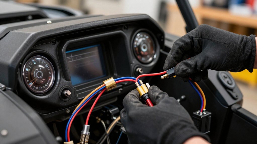
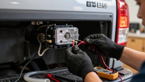
Turn off the key and disconnect the negative battery terminal; verify power is off with a multimeter.
Connect the kit to fused 12-volt power, following its diagram.
Tap the specified brake-switch output (the Dux kit’s gray/black lead), and splice the flasher’s labeled output into the turn-signal harness.
Wire the horn as directed; verify orange positive and white negative.
Seal splices with heat-shrink and route wires clear of heat and moving parts.
Test all functions; further checks can catch faults.
Brake, Horn, Flasher Hookup
Connect the flasher harness to a fused 12V source and verify its power and ground with a multimeter before finalizing the connections.
Use the kit’s harness leads to wire the horn button, then test the horn under light load before reassembly. Integrate the brake input with the supplied T-tap on the correct brake-light circuit wire; don’t identify it by color alone.
This connection should let the rear signals flash while preserving brake-light operation. Route horn and flasher wires clear of the drive shaft, coolant tubes, and steering or tilt hardware. Secure the harness along the OEM loom to prevent abrasion.
Power on and confirm the horn sounds and both left and right signals flash normally with the brake applied and released. Correct any fault before reassembly.
Brake and Horn Wiring Materials
With the flasher power and ground verified, gather the kit’s brake-light T-tap and designated switch lead, horn-button wire, fused 12V feed, ground lead, connectors, and tie-wraps.
Use the kit diagram to identify each connection; don’t infer function from wire color. The brake splice links the turn-signal function to the existing brake circuit, while the designated lead preserves normal brake-lamp operation.
Connect the column-mounted switch’s horn-button lead, or the supplied horn wiring, so horn control stays integrated with the turn signals.
Before routing, use these material checks:
- Match terminals to the kit diagram.
- Use fused 12V feed and specified ground.
- Secure connectors with tie-wraps.
- Route clear of heat and moving drivetrain parts.
Confirm braking illuminates lamps correctly and the horn sounds before operating your UTV.
Step 1: Disconnect Battery Before Wiring
Before touching any turn-signal wiring, turn the key off and disconnect the negative battery terminal so the fused 12V feed and brake-light input aren’t live while you splice. If your UTV has a battery disconnect switch, use it too, then verify the accessory circuit is dead with a multimeter. Keep the harness and flasher leads disconnected until the kit’s power, ground, brake-switch input, and horn connections are ready.
The flasher module and horn-button circuit can arc or short if grounded to the frame while you install connectors or T-taps. Route the harness clear of moving parts, including the driveshaft and axle, and confirm connectors are seated before reconnecting the battery. Then test horn and turn functions. Stop if your meter detects voltage; isolate the circuit first.
Step 2: Identify the Brake-Switch Lead
To keep braking and turn signals working correctly, identify the OEM brake-light switch output specified by your kit. Use the kit’s brake-light-switch integration diagram to locate the OEM circuit; don’t assume wire color alone identifies it. For the Dux kit, the gray/black harness lead connects to the brake-light-switch output with the supplied T-tap.
If your kit specifies a dedicated brake input, use only the identified brake-light circuit, not a nearby wire or an unrelated signal.
Before final assembly, check the lead with a multimeter or test light. Confirm its voltage or ground reference changes when you press the brake pedal; consult the kit diagram to interpret the reading. Keep wiring secured clear of the drive shaft, moving parts, and heat; reinstall panels without pinching it.
Step 3: Splice the Flasher Output
Once the flasher unit is identified, splice its labeled output wire into the harness lead for the left/right turn signals, following the kit diagram rather than guessing by wire color. Use the kit’s labeled colors or connectors to confirm the circuit, and connect any optional pilot or dash-indicator interface only where the diagram specifies.
If your setup uses diode jumpers, such as the PCS-72S arrangement, install them exactly as directed; they keep the indicator from responding to the wrong turn signal.
With power isolated, make each splice using a crimp and heat-shrink tubing or sealed connectors; a loose or exposed joint can corrode and cause intermittent clicking. Reconnect power and test both sides. Confirm consistent flashing, without hyperflash or no-flash, before securing harness.
Step 4: Wire the Horn Button
With the battery disconnected, connect the kit’s horn wiring to the dash or column button leads using the provided connector, and match any labeled leads on the flasher harness rather than tapping unrelated factory wires.
Connect the button before you mount it. Route the harness through existing dash openings, keeping it clear of pinch points under the dash and away from moving parts and hot surfaces. Use tie-wraps to secure the wires, but don’t pull them tight enough to crush insulation or restrict service access.
Check that no wire can snag on steering or suspension components. When routing and connections are complete, reconnect the battery and briefly press the button to confirm the horn sounds before closing the dash for final assembly.
Step 5: Mark Connector Polarity
Before plugging in any harness ends, use a multimeter to verify connector polarity, especially at the accessory feed: orange is positive (+) and white is negative (–) per the kit routing notes. Mark each lead with its function and polarity before you connect it; don’t rely on wire color alone.
For plate and indicator splices, match the kit’s specified pairs: black plate wire to orange, and white plate wire to grey. This prevents reversed power or illumination. At the horn connection, verify polarity and preserve the kit-specific flasher and horn assignments so the horn and turn outputs cycle correctly.
Take the T-tap brake-light input from the specified gray/black brake-circuit wire; otherwise, braking integration may not trigger the LEDs. After confirming connections, seat the connectors. Apply power and check that the correct sides illuminate and horn, hazard, and indicator behavior matches the kit’s operation.
Step 6: Protect Splices With Heat-Shrink
Seal each splice with heat-shrink tubing to keep moisture out and prevent corrosion-related failures. After you make the brake-light splice, often with the kit’s T-tap into the gray/black brake-light wire, select tubing sized to cover the splice and a short section of both wires. Use a heat gun to shrink tubing evenly until it seals tightly; keep the tubing centered and avoid overheating insulation.
Repeat for the horn and flasher connections, sealing each crimped or solderless junction before routing the harness. For diode or jumper circuits, seal every junction too; corrosion can cause intermittent clicking. Keep joints away from moving components, including the drive-shaft tunnel area, and inspect the splice zone for exposed copper before securing the harness with suitable ties and maintain clearance.
Verify Hazard-Light Synchronization
Once the splices are sealed and the harness is routed, press the hazard switch and confirm the TSS flasher produces the correct turn-cycle timing through its pilot or flasher output, where fitted.
Check the dash indicator: on supported Polaris round-style and Can-Am X3 clusters, its LED should blink with the hazards. With brake integration, confirm hazards flash both rear lamps through the harness splice, then verify brake operation stays normal when you press the pedal. Before assembly, use a multimeter to ensure hazards don’t change the brake-light input state used for rear-output logic.
Reconnect the harness; test hazards and left/right turns for hyperflash or desynchronization, which may signal an LED/flasher mismatch or incorrect pilot connection. Fix faults before riding, and secure all wiring properly.
Brake Lights Stay On
Brake lights that stay on usually indicate a miswired or continuously energized brake input. First, verify the T-tap connects to the kit’s specified brake-switch lead, such as gray/black. Use a multimeter: voltage should appear only when you press the pedal.
| Check | Expected result | Correction |
|---|---|---|
| Brake input | Hot only pressed | Verify specified lead |
| T-tap splice | Secure contact | Check insulation contact |
| Dash connectors | Fully seated | Reconnect securely |
| Flasher ground | Correct ground | Verify polarity |
Seat connectors; confirm flasher ground. Test after reassembly: pedal released, lamps off; pressed, lamps on; indicators cycle normally only on command.
Inspect Harness Chafe Points
With the brake-light circuit checked, inspect the complete harness pathway for chafe risks before connecting power, especially near the drive shaft, coolant tubes, and steering-column adjustment area, where motion can pinch or abrade wires. Secure any section routed under the tunnel or console along the OEM harness and fasten it with zip ties so the loom can’t shift against sharp metal edges. Check each grommet and drilled hole; ensure grommets seat and wires don’t contact bare sheet metal.
Keep clearance from exhaust heat and brackets, adding heat-shrink or loom where wires turn or cross metal. Gently tug each plug and wire to verify strain relief. Nothing should feel tight, hanging, or rubbing when the suspension compresses. Recheck the route through travel before reconnecting power.
Conclusion
Before you power the UTV, confirm each brake, horn, and flasher connection against the kit diagram. Keep the battery disconnected while you correct wiring, and secure every splice with heat-shrink.
Then reconnect power and test brake lights, turn signals, hazards, and the horn in place. Verify hazards flash together, brake lamps release correctly, and no wiring rubs or stays energized. If anything behaves unexpectedly, don’t drive; disconnect the battery and inspect your connections before driving.