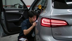
How to Wire Auxiliary Reverse Lights With a Manual Override Switch
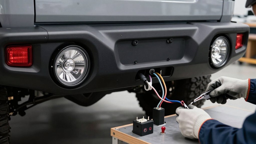
You can wire auxiliary reverse lights through a fused relay, keeping lamp current off the switch and factory reverse circuit.
Connect battery power through an inline fuse near the battery to the relay, then connect the lamps to its load output and ground.
Feed relay control from the reverse trigger and manual switch using an isolated control arrangement.
Disconnect the battery first.
Verify Off, Brakes, and Reverse states, seal splices, and aim beams downward.
More checks follow.
Manual Override Behavior
A manual override lets you switch auxiliary reverse lights on when needed, even when the vehicle isn’t in reverse. With the circuit configured to accept both a manual command and the vehicle’s reverse-light signal, you retain automatic operation. The lights come on when you select reverse, while the switch gives you control outside that gear.
This combined behavior supports backing assistance when you need extra rear illumination without shifting into reverse. Use the override only when the area behind you is clear, and remember that bright auxiliary lights can obscure other drivers’ vision. Turn them off when they’re no longer needed.
Confirm that the lights respond independently to the switch and automatically to reverse before relying on either function on the road with care.
Gather Wiring Supplies
Before you begin wiring, gather the correct-gauge wire, crimp connectors, an inline fuse sized for the auxiliary lights, and the switch and relay hardware. Use a multimeter or test light to identify the reverse-light lead; Black/Pink may appear on more than one circuit. Check each in Off, Brakes, and Reverse states before tapping it.
Prepare wire runs and connectors before you enter tight areas, so you can route without rework. Keep the fuse as close to the battery as possible, and protect conductors from abrasion at openings or grommets.
- Match wire gauge to current load and run length.
- Choose butt connectors and ring terminals sized for the wire.
- Select a fuse rating for auxiliary lamp draw.
- Ensure the switch and relay use compatible power and ground plans.
Step 1: Mount the Override Switch
Choose a switch location on the dashboard or center console that’s easy to reach from the driver’s seat, then check for clearance behind the panel for the switch body, connector, and wiring. Check for hidden components; mark the opening to the switch maker’s dimensions. Deburr the cut edge and protect exposed metal.
Secure the switch with its supplied nut or bracket; tighten it without deforming the panel. Route the connector and wiring along the planned path, clear of sharp edges, moving controls, and heat. Plan the circuit to share the relay control circuit’s power feed and ground. Confirm terminal orientation for manual relay activation or automatic reverse-control operation. Mark the selected position ON/MANUAL so you can identify it during later testing with a multimeter or test light properly.
Step 2: Disconnect the Battery
Because you’ll be working near the fusebox and relay connections, disconnect the vehicle’s battery before touching the reverse-light wiring.
Switch off the ignition and remove the key, then follow your vehicle’s manual to disconnect the negative terminal first. Keep it clear of the battery post to prevent accidental contact.
Plan the feed route from the fuse location near the battery through the cab grommet with power isolated; don’t energize the circuit during installation. If you’ll expose reverse-light wire insulation for multimeter testing, confirm its location first and work only with the battery disconnected.
Keep the battery disconnected while removing feeds or splicing leads, and before attaching ring terminals, inline fuses, or butt connectors. Reconnect the battery only after you’ve crimped, wrapped or taped, and tucked away every terminal, preventing accidental contact during the initial power-up.
Step 3: Wire the Relay Control Circuit
With the battery still disconnected, plan the relay control circuit so the auxiliary lights can operate manually or follow reverse gear. Use a relay and manual switch to command the lights independently of reverse gear. To retain automatic operation, reserve a separate reverse trigger path, distinct from the load wiring.
Share the switch and relay-control ground/power reference, then split one feed into two outputs with a properly sized butt connector. Choose suitable coil wiring and protect every splice against shorts. Plan routing through grommeted body pass-throughs; secure the loom away from sharp edges and moving parts to prevent pinching or cutting a hot lead and blowing a fuse.
Verify the vehicle diagram before proceeding. Keep the control circuit simple, labeled, and accessible for inspection.
Step 4: Connect Reverse-Light Trigger Wires
Before connecting the automatic trigger, locate the reverse-light wire behind the driver’s kick panel; pull back the rubber cover at the rear edge to expose the harness. Some trucks have two Black/Pink candidates, and harness locations can vary by year or model. Don’t depend on color alone.
Ground your multimeter’s black probe, then touch its red probe to a small shaved point on each wire. Keep clear of moving parts and prevent the probe from bridging adjacent conductors. Check each candidate through Off, Brakes, and Reverse; choose the lead that activates when reverse is engaged. If needed, test likely wires in the kick-panel area until one responds correctly.
Once confirmed, route that trigger wire to the relay or switch input specified by your circuit, securing it away from sharp edges. Disconnect the battery before making connections, and insulate the test point afterward. This ensures your auxiliary lights receive the correct reverse signal.
Step 5: Aim Lights Below Sightline
Aim auxiliary lights below the vehicle’s sightline so they illuminate the area low and forward without blinding other drivers. Set each housing at the rear and angle its beam downward toward the ground behind the truck. Choose a level surface, then check the beam from the driver’s seat and from behind the vehicle. Keep the bright hotspot below the sightline and avoid aiming toward mirrors or nearby traffic.
Plan the wiring route before securing the lamps: ensure you can access the run under the dash before routing it rearward beneath the cab. Use existing grommeted pass-throughs to protect the cable from sharp edges; don’t let the route interfere with pedals or moving parts.
Verify the aim with the override on and off before driving.
Step 6: Weatherproof the Splice Connections
Once the lights are aimed, seal every splice with a properly sized insulated butt connector or crimp splice and adhesive-lined heat-shrink tubing. Before sealing, inspect each conductor, remove stray strands, and tug-test every crimped joint; a loose connection can admit moisture or create a short. Cover exposed relay and terminal connections with electrical tape only as a temporary measure, then finish them with heat-shrink for a weatherproof barrier.
Use a heat source carefully, keeping it clear of fuel, insulation, and heat-sensitive materials. Confirm the tubing has fully contracted around the splice, with no uncovered wire ends or conductor tails. Route each joint away from moving parts and pinch points, then secure the harness to prevent tension and repeated flexing. Leave enough slack for movement without allowing wiring to rub on sharp edges. Don’t rely on tape alone: water can travel beneath it and corrode conductors.
Test Reverse-Light Interlock
To verify the reverse-light interlock, identify the correct trigger wire—often Black/Pink, though two wires may share that color—using a multimeter or test light.
With secured and ignition off, inspect the candidate wires. Expose a section of insulation to create a test point, then connect the meter’s black lead to chassis ground. Set the meter to measure voltage, or prepare the test light.
Check each wire in three states: Off, Brakes, and Reverse. Have an assistant operate the controls.
Choose only the wire that becomes hot in Reverse and stays inactive during Off and Brakes. That wire is the override’s interlock trigger. Insulate the test point afterward. Confirm the interlock works before running power to auxiliary reverse lights; this prevents incorrect switching and blown fuses.
Relay Chatters After Installation
If the relay chatters after installation, its control circuit may be unstable even when the trigger wire appears connected. Use a multimeter or test light to verify the actual Black/Pink feed through Off, Brakes, and Reverse; two wires may share that color, and the wrong one can toggle the relay. Check switch and relay hot feeds and grounds in the tight kick-panel or driver-seat area for loose connections or intermittent shorts.
If you modified a grommet under the cab or seat, inspect the hot wire for nicks before testing again. Feed relay power through an in-line fuse near the battery.
| Check | Expected result |
|---|---|
| Trigger | Off: no feed |
| Brakes | Confirm state |
| Reverse | Feed steady |
| Wiring | Hot and ground secure |
Isolate power before you repair any damaged wiring.
Inspect Fuse Holder Corrosion
Before inspecting the fuse holder, disconnect battery power to prevent a short. With power isolated, remove the fuse and inspect the clips, exposed metal, inline connections, and ring-terminal or fusebox mounting points. Green or white oxidation, looseness, or pitting can raise resistance and cause intermittent lamp power.
Clean sound contacts with an appropriate electrical-contact cleaner; replace corroded clips, terminals, or the holder rather than relying on scraping damaged metal. Confirm the holder sits as close to the battery as practical, and protect its connection area from water and road spray.
Check that taped or wrapped relay and power terminals remain sealed, especially where the hot feed enters the cabin or passes through body openings. Reconnect power, then use a multimeter or test light at the reverse-light input. Verify solid voltage in Off, Brakes, and Reverse modes.
Conclusion
Confirm that the auxiliary lights turn on in reverse and that your override works only as intended. If the relay chatters, switch off the system and inspect the control wiring and ground. Check the fuse holder for corrosion, and replace damaged parts before testing again.
Secure every connection, restore the battery connection, and verify operation in a safe, stationary test. If you can’t confirm correct interlock behavior, disconnect the lights and have a qualified technician inspect the circuit before driving.