What Makes a Quality LED Light Bar? The Specs That Actually Matter
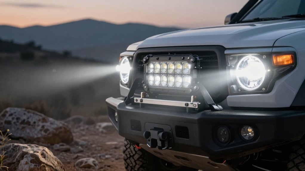
A quality LED light bar delivers controlled, usable light, not just high claimed lumens. You’ll assess the LED and TIR optic pairing, beam pattern, and aiming, plus a metal-core board with a direct thermal path.
Check the sealed housing, impact-resistant lens, dust and weather ratings, condensation vents, and vibration and temperature testing.
Measure voltage at the leads under load; verify connectors, harness, mounting fit, terrain needs, and road-use limits.
The following sections show what matters most in practice.
Specs That Define Quality
A quality LED light bar depends on how effectively it controls and manages light, not just on emitter output. When you compare specifications, examine the emitter-optic pairing: high-intensity LEDs, such as Luxeon Z ES 5700K units, should work with efficient total internal reflection (TIR) optics to direct light forward and limit spill or glare.
Check thermal construction, too. Metal-core circuit boards and direct thermal paths help move heat away from components, supporting stable operation and service life. For harsh conditions, verify weather ratings, double-wall molded gaskets, and an operating range near -40 to 185°F.
A breather vent in each six-inch section can reduce condensation and corrosion. Finally, inspect wiring compatibility: durable DT-type Deutsch-style connectors, suitable pigtails, and a matched harness and voltage rating matter.
Beam Pattern Efficiency
Beam pattern efficiency depends on optics that capture LED output and direct it where you need it. Total internal reflection (TIR) optics control LED’s output, limiting spill that inefficient reflectors scatter widely. A 20-by-8-degree driving pattern concentrates intensity downrange, helping you spot obstacles with more useful light per LED than an overly wide beam. An 80-by-50-degree flood pattern spreads illumination across trails and sides, improving awareness without relying on brute-force brightness.
For bars 18 inches or longer, combo designs can pair driving and flood optics to balance distance with visibility; they outperform a generic single pattern. Correct aiming also reduces glare and wasted photons, so you can see while limiting light reflected toward you or other drivers. Choose the distribution that matches your route, not the highest output.
Voltage Drop Under Load
Even well-matched optics can’t compensate for voltage lost in the wiring under load. When a long, high-output bar draws current, resistance in its wiring, connectors, and ground reduces voltage at the bar below battery voltage. Undersized wire, poor crimps, or a weak or dirty ground can create enough drop to lower the LED driver’s input voltage and reduce effective brightness.
For multiple bars or long runs, target roughly 3% maximum drop, about 0.36V on a 12V system, to keep output consistent. DT/Deutsch-style connectors can limit resistance, but you must crimp and seal them correctly to prevent moisture and corrosion from increasing resistance over time. If a bar dims at idle or during acceleration, alternator/battery behavior may contribute. Measure voltage at leads under load to confirm.
Housing and Lens Materials
Assess the housing for durable materials and effective heat transfer, since controlled temperatures protect LED output and service life. Check that the lens stays clear and strong while its optics direct usable light and limit glare.
Inspect the seals and weatherproofing for resistance to moisture, vibration, and temperature cycling.
Housing Material Durability
A quality LED light bar needs a rugged housing, typically aluminum or another metal-core design, to dissipate heat and withstand vibration and impact better than a thin plastic shell. Check wall thickness, joint rigidity, and mounting points; even strong alloy can fail when the enclosure flexes or fasteners loosen under repeated shock.
Metal-core circuit boards and thermal slugs move heat away from LEDs, helping components stay within safe operating temperatures.
Assess weather sealing as part of the housing system: double-wall construction and custom-molded gaskets, sometimes fitted by section, limit moisture entry that can corrode connections and damage electronics.
Finally, choose a bar rated for severe thermal cycling, ideally about -40°F to 185°F; stable materials reduce warping, condensation, and premature seal failure over time.
Lens Clarity and Strength
Beyond a rugged housing, lens quality determines how cleanly an LED light bar delivers its beam and withstands abuse. Look for purpose-built TIR optics or reflectors that keep light focused across the intended beam pattern; poorly designed surfaces scatter output and increase glare. That distinction matters when you need usable illumination rather than brightness figures alone.
You should also check the lens material: impact-resistant polycarbonate tolerates strikes and vibration better than thin, brittle plastics, which can crack or haze and reduce transmission. Pair it with a rigid, double-wall housing and properly bonded components. This structure limits flex under impact and vibration, helping preserve lens alignment and protect internal optics. Heat paths also limit thermal stress that can cloud or distort the lens over time, too.
Seals and Weather Resistance
At the housing and lens, effective weather resistance depends on more than a water-resistant coating. Look for a double-wall housing with custom-molded gaskets; these seals limit moisture intrusion as temperatures swing. Verify how the bar divides into sealed segments: gasketed six-inch compartments can contain a leak rather than expose the unit.
Your lens and housing must tolerate impact and thermal cycling, while a metal-core polycarbonate circuit board inside the sealed enclosure supports stable operation.
Check that each sealed segment has a breather vent to reduce condensation and fogging as the bar heats and cools. Then review testing, not marketing claims: confirm operation from -40°F to 185°F and vibration, moisture, and corrosion tests aligned with SAE/DOT standards. These results help you assess durability under exposure.
Heat, Dust, and Vibration
When you run an LED light bar hard, effective thermal management keeps its LEDs within operating limits. Sealed construction limits dust and moisture ingress that can degrade electronics over time.
For off-road use, vibration-resistant design helps prevent loose components and cracked solder joints.
Thermal Management
Although a light bar’s housing sheds heat, its circuit board must conduct it away from the LEDs to keep junction temperatures stable under continuous load. Look for a metal-core polycarbonate board and a direct thermal path into the housing; these features limit thermal resistance rather than merely spreading heat across the board. Ask for operating data across roughly -40°F to 185°F, since repeated temperature swings can expose weak heat transfer or sealing and trigger early failure.
On sectioned bars, breather vents, ideally one per six-inch segment, plus durable internal seals can reduce condensation that otherwise impairs heat dissipation. You should also verify vibration testing alongside moisture and corrosion tests: vibration can loosen connectors or damage components, while accumulated damage becomes more consequential as heat stresses the assembly. Judge these results under sustained load, not just brief bench operation, because stable junction temperature protects output and service life over time.
Dust Ingress Protection
Thermal management depends on keeping fine dust out of the housing: deposits can impede heat transfer and cooling, raising the risk of premature LED or driver failure.
A strong IP rating helps you assess how effectively the enclosure blocks fine particles. But an IP rating alone won’t show how well the bar manages heat after exposure. Effective thermal design pairs sealing with conductive paths: metal-core polycarbonate circuit boards and direct solder thermal slugs carry heat away even in dusty conditions.
Custom molded gaskets and segmented seals limit leak paths as temperatures cycle. For example, double-wall weatherproof sealing across six-inch sections can help preserve enclosure integrity. A breather vent per section can reduce condensation and fogging, which can otherwise promote contamination.
Check the specified IP level and sealing design together; you need both dust exclusion and a reliable route for internal heat to escape. This balance extends service life.
Vibration Resistance
Choose a light bar tested to SAE/DOT vibration standards to withstand constant chassis movement without performance loss. Those tests matter because repeated shaking can loosen connections, stress solder joints, and shift optics. Check that the manufacturer verifies performance after vibration exposure, not just initial brightness.
Also assess the system around the LEDs: metal-core polycarbonate boards with direct-solder thermal slugs help manage heat cycles across tested operating temperatures of -40 to 185°F. Double-wall weatherproof sealing, including molded gaskets on six-inch segments, limits dust and moisture that can trap heat or degrade optics and seals. A breather vent can reduce condensation as temperatures swing.
You’ll get better long-term stability when the bar survives the full heat-to-cold-to-vibration sequence, rather than relying on a high output rating alone.
Nighttime Trail Visibility
How well you see a trail at night depends on matching the beam to the terrain: a narrow driving pattern around 20×8 degrees helps spot obstacles downrange, while an 80×50-degree flood pattern lights the trail’s sides. Choose TIR (total internal reflection) optics to direct output toward useful areas rather than scatter it, reducing glare. Use amber in fog or other low-visibility conditions; white delivers maximum brightness when air is clear.
| Beam | Best condition | Visibility role |
|---|---|---|
| Driving | Downrange spotting | Narrow reach |
| Flood | Trail edges | Wide side coverage |
| Thermal/sealing | Long outings | −40 to 185°F; vents limit fogging |
Check fit: bars under 42 mm tall span 6 to 50 inches, covering trail without crowding your mount. Confirm −40 to 185°F testing, weather sealing, and breather vents per section to limit moisture and condensation.
Road-Legal Use Restrictions
A beam suited to trail visibility isn’t automatically legal on public roads: rules vary by state and may restrict a light bar’s type, size, brightness, or use to off-road driving.
Before you buy, check your state DMV or official guidance for permitted designs and operating conditions; don’t infer legality from a product label. Many jurisdictions restrict bars as blinding, so SAE-pattern compliance matters.
For driving lamps, look for a white SAE J581 beam, assessed as a pair and aimed under state rules. For foglamp use, check for a white or amber SAE J583 pattern. Approval doesn’t remove installation duties: you may need accurate aiming, paired mounting, or a cover while driving on public roads. Treat road use as a separate requirement from trail performance.
Comparing Claimed and Measured Lumens
A claimed lumen figure tells you how much light a bar may emit, not how much reaches the road. Compare that number with measured beam data, because optics shape useful illumination and aiming determines where it lands. A rating alone can’t establish what you’ll see on-road.
- Ask whether testing used an integrating sphere or standardized candela and beam measurements; methods can yield different lumen values.
- Compare beam patterns, not claims alone: a TIR optic can concentrate output into a tighter driving beam for greater downrange visibility than a wide flood.
- Check applicable SAE J581/J583 compliance and measured glare; high output isn’t automatically practical or road-safe.
- Review sustained results after heat and vibration testing; efficient optics and thermal management can limit output decline over time.
Verify Mounting Bracket Fit
Will the bar fit without compromising its mounting or sealing?
Before buying, confirm the bar’s physical height and length against your installation space. A low-profile design under about 42 mm may clear a bumper lip, grille opening, or tight roof or winch area, but measure your vehicle rather than assume. Match available bar length, from roughly 6 to 50 inches, to your mounting span so the brackets meet the bar’s mounting points without forcing an angled or unstable install.
Then verify the bolt pattern and end-cap or rail geometry. Don’t rely on “universal” claims: narrow housings can use specific spacing. Check that the bracket won’t pinch or misalign sealed segments, including double-wall designs with molded gaskets. Finally, preserve clearance for the pigtail or Deutsch-style connector, keeping wiring accessible and free of strain during installation.
Conclusion
Choose a light bar by measured performance, not headline numbers. Check beam efficiency, voltage drop at operating load, and whether the housing, lens, and thermal design can withstand dust, vibration, and heat. Then assess usable trail visibility, confirm road-use restrictions, and verify bracket compatibility before installation.
You’ll get a dependable setup when the bar’s real output matches your vehicle, terrain, and wiring capacity. Ignore unsupported lumen claims; prioritize documented tests, fitment details, and specifications.