How to Wire Ditch Lights on a Ford Bronco With Upfitter Switches
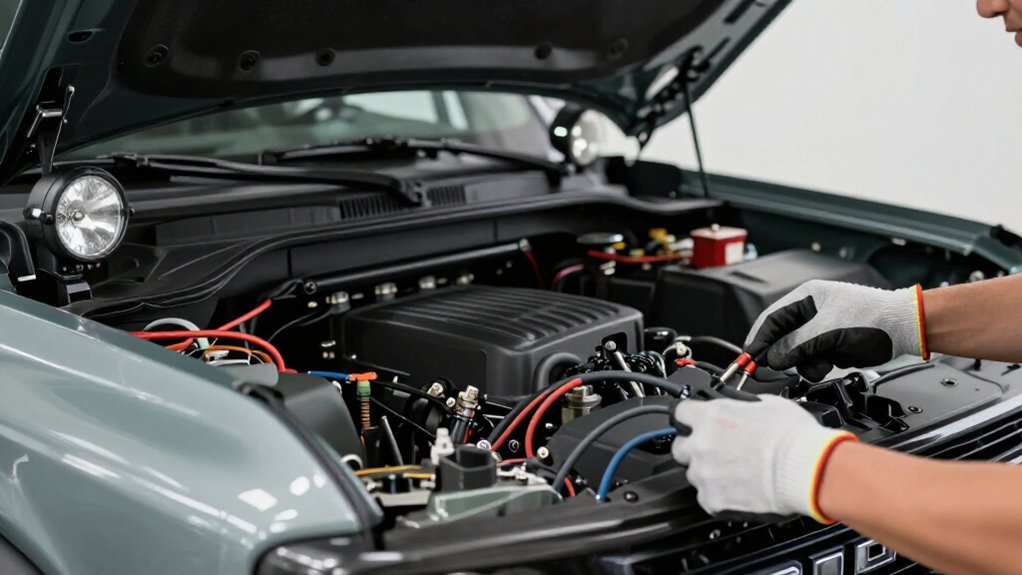
Check your Bronco’s upfitter rating before wiring; Aux Switch 6 typically supplies a fused 10-amp feed, so add both lamps’ current and stay within its limit.
If they exceed it, use a separately fused battery feed for the relay’s load side.
Disconnect the negative battery terminal, route protected wiring through a grommet, and secure it away from heat and moving parts.
Label circuits, test operation, inspect seals, and use the checks below for reliable results.
Factory Switch Load Limits
Before wiring your ditch lights, check the Bronco’s upfitter switch rating and the combined current demand of both lamps.
Aux Switch 6 typically provides a fused 12-volt feed, rated at 10 amps. Add both lamps’ current requirements and compare their total with the switch’s limit. Exceeding that rating can overheat wiring or blow the fuse.
If the combined draw is too high, don’t power the lamps directly from the factory switch. Use a fused battery feed for the relay’s load side, and connect the upfitter output only to the relay’s low-current control side. Check that the switch energizes only when the key is on. Ensure no unused harness power lead remains connected to a live upfitter output; that could bypass the low-load control path.
Heat-Shrink Connector Selection
For the Rough Country 70904 harness, choose dual-wall, adhesive-lined heat-shrink butt connectors sized to each wire gauge, including the relay leads and light power and ground conductors. Before crimping, confirm each connector accepts the conductor and insulation, allowing full crimp contact without forcing strands.
- Match the connector’s range to the harness wire gauge; don’t assume relay and lamp leads are identical.
- Select dual-wall tubing with suitable shrink ratio and diameter for the terminal and insulation thickness.
- Confirm its automotive voltage and current rating covers the harness feed and any tapped AUX 10A circuit.
- Heat evenly until adhesive flows at both ends; let the joint cool before checking.
After cooling, pull-test each connection and inspect both ends for a continuous seal. Use steady, controlled heat.
Step 1: Route Wiring Through Firewall
At the factory firewall grommet, plan a protected route from the engine bay to the upfitter-switch area, keeping the fused red power wire clear of pinch points.
Use an existing rubber grommet. If you must drill an opening, fit a proper grommet before passing relay and harness leads through. This protects insulation from sharp metal edges. Keep the high-current fused feed separate from low-current switch-control and signal wires to reduce unintended energizing.
Secure the harness every six to eight inches with P-clips or zip ties. Route it clear of hot exhaust parts and moving components such as the fan and belts. Before tightening and fuse or relay hookup, verify your upfitter circuit—AUX Switch 6, for example—supplies power only when expected in key-on and key-off states.
Step 2: Disconnect Negative Battery
Once the harness is routed, disconnect the negative battery terminal to prevent accidental shorts while you connect the black ground and red power leads. Keep ignition off, remove the negative cable from the battery post, and secure it so it can’t spring back into contact.
With the circuit isolated, terminate the black ground wire at a clean vehicle ground point; don’t leave it touching metal temporarily. Leave the inline fuse on the red lead, but don’t make the final AUX connection yet; the battery-side feed can become live after reconnection.
Don’t test the relay or lights now. First confirm the control wire reaches the intended AUX switch. After wiring, reconnect the negative cable and verify key-on operation: lights should energize only when the selected AUX switch is on.
Step 3: Mount Ditch Light Brackets
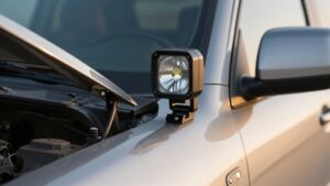
Position each ditch-light bracket on the A-pillar or fender edge, checking that the light clears the hood and windshield hardware through the suspension’s full travel. Use the supplied brackets and hardware to fasten each bracket to solid sheet metal or a structural mounting point; don’t attach it to thin trim, which can loosen under repeated bumps.
Before tightening the bolts, slide the light into place and check its aim. Set the lens for your intended down-road pattern; make sure it doesn’t point into the hood or ground.
Route the wire along the bracket’s inside edge, then secure it with zip ties to prevent chafing on the bracket lip. After mounting, gently push the housing to confirm it’s seated. After test-driving, recheck bolt tightness again.
Step 4: Splice Lights to Upfitter Leads
With the battery disconnected, connect the harness’s relay trigger wire to a dedicated upfitter lead, such as AUX Switch 6, so the relay energizes only when the circuit has key-on power and the switch is on.
Confirm the harness uses this lead as a switch input; then restore power and verify the relay stays silent with the key off and AUX Switch 6 off. Follow the harness diagram before joining the lights’ high-current red leads, since you should combine them only in its intended configuration, often at one upfitter-fed power wire.
Keep the inline fuse in that power path. Join each black light lead to a clean, secure factory chassis ground, not thin factory wiring, to limit voltage drop and relay faults. If unused three-wire switch conductors remain, isolate them as directed by the harness maker; don’t let them backfeed the trigger when you’re using one AUX channel. Insulate and secure every splice before reconnecting the battery and testing operation.
Step 5: Aim Lights Below Hood
After securing the splices, aim each ditch light so its beam falls just below the hood line, then check alignment from the driver’s seat. Park level, facing a flat surface, and secure the vehicle. Keep the engine off while adjusting brackets; avoid hot components and moving parts.
Set each beam low enough to clear the hood without lighting its edge; tighten mounts and recheck from the seat. Choose a key-on AUX switch, such as AUX 6, and verify the relay indicator responds only with ignition on. Battery should feed the relay’s high-current path; the upfitter switch should feed only its control side.
Confirm control and ground connections prevent relay activation with the switch off. Secure unused leads away from heat and moving parts. If separate blue and white controls exist, test each.
Step 6: Label Each Switch Circuit
Before routing the harness, label each circuit at both ends with its exact Bronco upfitter switch number, such as AUX Switch 6, so you can identify which relay trigger should be hot with the key on.
Mark every wire at both ends before routing: relay trigger, battery or direct power input, and each beam lead if your harness separates high and low beams. If a three-lead switch uses blue and white for separate high/low circuits, label each with its assigned AUX number; mark black as ground, not switched power. Identify black grounds and red switched feeds through the harness fuse. Add behavior notes to your diagram: AUX Switch 6, 12V, 10A fuse; the relay should energize only when that labeled switch is on.
Test Lights With Ignition on
Once the circuit labels are in place, turn the key to ON and check that the assigned AUX feed, such as AUX Switch 6, delivers 12V and energizes the relay so the ditch lights turn on.
Leave the inline fuse on the red lead installed. Confirm the harness ground, often black, has continuity to solid vehicle ground; this rules out a grounding fault. With AUX on, verify the lights illuminate.
Then turn the key OFF: the harness and relay must stay off. If they energize, inspect the relay signal circuit for unintended power before proceeding. Turn AUX off and confirm its indicator is dark when key-on-only operation is expected. Keep clear of moving parts and avoid exposed live conductors throughout the entire test procedure.
Voltage Drop at Switch Leads
Because voltage drop in the switch leads can weaken or destabilize relay operation, measure voltage at the upfitter output and relay signal wire with the lights on. Use a multimeter to measure both points under load; even a drop across wiring or terminals can alter coil pull-in or holding.
Seat ring terminals and crimps tightly; loose grounds or high-resistance joints can cause greater loss than the switch. Route signal leads away from heat and avoid loops or unused bundled conductors that add resistance and distort readings. If relay behavior changes with key state, switch it off and check the coil lead for unexpected voltage; trace shared wiring before use.
| Check | Action |
|---|---|
| Loaded voltage | Compare readings |
| Connections | Secure terminals |
Inspect Seals After Rain
A stable relay signal is only part of a reliable setup; after heavy rain or a car wash, inspect the ditch-light housing seam and wire-entry grommet for signs of water entering the lens area.
After inspection, check that harness and relay connections remain sealed. Inspect the inline fuse holder and quick-disconnect fittings for moisture or corrosion. Follow the A-pillar and hood-edge routing; confirm loom or tape hasn’t lifted and exposed bare conductors.
If you find droplets inside the housing or on connectors, disconnect the harness. Dry them, then reseat or replace damaged seals before driving. Don’t energize wet connections.
After everything’s dry and sealed, test lights again using the upfitter switch. Watch for intermittent flicker, which can indicate moisture-related connection trouble.
Conclusion
Before driving, confirm each ditch light works on its labeled Bronco upfitter switch, check for excessive voltage drop, and verify the circuit stays within its factory load limit. Secure and inspect all wiring, connectors, firewall seals, and brackets; repair any loose or exposed connections before use.
After the first rain, check the seals again for moisture. If a circuit overheats, a fuse opens, or the wiring behaves unexpectedly, disconnect the battery and have the installation inspected before operating the lights.